
Copper based sintered contact material and double-layered sintered contact member

a contact material and copper-based technology, applied in the direction of metal-layered products, basic electric elements, electrical appliances, etc., can solve the problems of poor comformability and a limitation of use under high load, wear resistance, and inability to ensure long-term durability

Inactive Publication Date: 2005-01-18
KOMATSU LTD
View PDF9 Cites 50 Cited by
  • Summary
  • Abstract
  • Description
  • Claims
  • Application Information

AI Technical Summary

Benefits of technology

(1) By properly selecting non-metallic hard dispersion particles such as ceramics and intermetallic compound particles (hard, first dispersion particles) which have good agglutination resistance with respect to iron (mating material) and good thermal shock resistance and properly determining the amount of the above materials and the size of the dispersed phase, an action for scratching off agglutinates locally existing on the sliding contact surface is caused so that improved seizure resistance and wear resistance are obtained while reducing attacks on the mating material.
Further, the inventors have studied how to add Sn in order to restrain the sinter shrinkage of the dispersion layer having a composition of a bronze based sintered contact material and found the following technique: A Cu—Sn based alloy powder at least containing Sn in an amount more than Cu—30 wt % Sn and / or an Sn primary powder are used. The powder which is the source of Sn is first melted in the first sintering, reacting to the surrounding Cu and / or the Cu—Sn based alloy powder containing 12 wt % or less Sn, whereby the sintered dispersion layer is expanded while forming β, γ, ζ, δ, ε and η phases (see the Hansen's Cu—Sn binary phase diagram). Thus, sinter bondability is more effectively achieved.

Problems solved by technology

However, this technique has revealed a problem in the durability and service life of the overlaid layer when the lead bronze based sintered contact material is used under higher surface pressure or in a condition where boundary lubricity increases because of additional conditions (e.g., vibration load and acceleration / deceleration) imposed on the material while the material being subjected to sliding contact.
On the other hand, lead bronze based and lead copper based sintered contact materials which contain large amounts of Pb suffer from the following problem: If they are used in a condition where, among others, sliding speed is high, or where acceleration and deceleration are repeated with changes in the rotating (sliding) direction so that sliding speed greatly changes, or where the mating material has high surface roughness, wear resistance will rapidly increase and as a result, sufficient durability cannot be ensured for long use.
The aforesaid high strength brass should be utilized if importance is given to the improvement of the wear resistance of a contact material, but it is normally hard, having a hardness of Hv 180 or more and therefore presents the drawbacks of poor comformability and a limitation to use under high load, low speed conditions.
In addition, high strength brass has significantly high vapor pressure and a high concentration of highly oxidable Zn so that it cannot be bonded to steel by casting.
Brass based sintered contact materials are also extremely difficult to be sinter bonded to, for instance, iron based materials because of the high Zn concentration of the brass based material, and therefore they cannot be utilized in sinter bonding to cylinder blocks and valve plates.
The technique disclosed in the above publication has, however, an economical problem because the W particles to be dispersed for forming a lubricating oil film need to be contained in a large amount (3 to 13 wt %).
The W particles are not hard enough and therefore a satisfactory function for scratching off the local agglutinates cannot be achieved for stopping the growth of the agglutinates.
As a result, a satisfactory improvement in wear resistance cannot be expected and moreover, the generation of a large amount of powder agglutinates leads to a failure in achieving a satisfactory improvement in seizure resistance.
This technique has proved unsuccessful in that, like Japanese Patent Kokai Publication No. 11-350008, the hardness of the Mo particles is not hard enough, entailing an unsatisfactory improvement in wear resistance and the generation of a large amount of agglutinated powder leads to an unsatisfactory improvement in seizure resistance.
This producing method involves pressure sinter bonding and therefore imposes many geometric restrictions on its applications as well restrictions on equipment to be employed, which results in not only poor productivity but also high production cost.
A large amount of Sn or the like also flows out together with Pb so that not only large amounts of Sn and Pb cannot be contained in the above sintered contact material but also the flow-out of Sn and Pb through the production process causes an environmental problem.
This technique has however revealed the problem that since molybdenum disulfide and tungsten disulfide tend to be decomposed into hard copper sulfide (Cu2S) during sintering, it becomes necessary to add these disulfides in large amounts in order to ensure sufficient lubrication.
This results in brittleness in the sintered compact and an increase in the cost.
Graphite does not react to a bronze based or lead bronze based sintered material, markedly restrains the sinterability of the sintered compact, weakens the strength of the sintered material, and is hardly wet by Sn rich and Pb rich liquid phases which are generated during sintering.
Therefore, addition of graphite presents the problem that sweating becomes significant during sintering, producing a number of melt-off pores.
In addition, boundary lubrication is promoted by the facts that as the amount of residual graphite increases, it becomes more difficult to compact the sintered layer and that graphite is a porous substance.
In consequence, sliding properties under high-speed oil lubricated conditions cannot be improved as much as expected.
(2) Since the non-metallic powders are high in hardness, they cause excessive wear of their mating material.
(3) Since a large amount of the non-metallic material is unlikely to be bonded to the metal base, the strength of the sintered compact decreases and the wear resistance of the friction material itself is insufficient. Further, the non-metallic material is likely to drop off the friction surface so that the dropped powder sometimes galls other parts than the friction area.
(4) The friction materials and their mating materials are designed on assumption that they are periodically replaced as consumables.
However, it is apparent that the friction coefficient of this material is so high that it cannot be utilized as a bronze base contact material and this material also suffers from the same problem as described earlier.
The dispersed alloy powder shrinks more significantly than the lead bronze based material during sintering and therefore the alloy powder cannot be sinter bonded to the steel plate.

Method used


Image

  • Copper based sintered contact material and double-layered sintered contact member
  • Copper based sintered contact material and double-layered sintered contact member
  • Copper based sintered contact material and double-layered sintered contact member

Examples


example 1

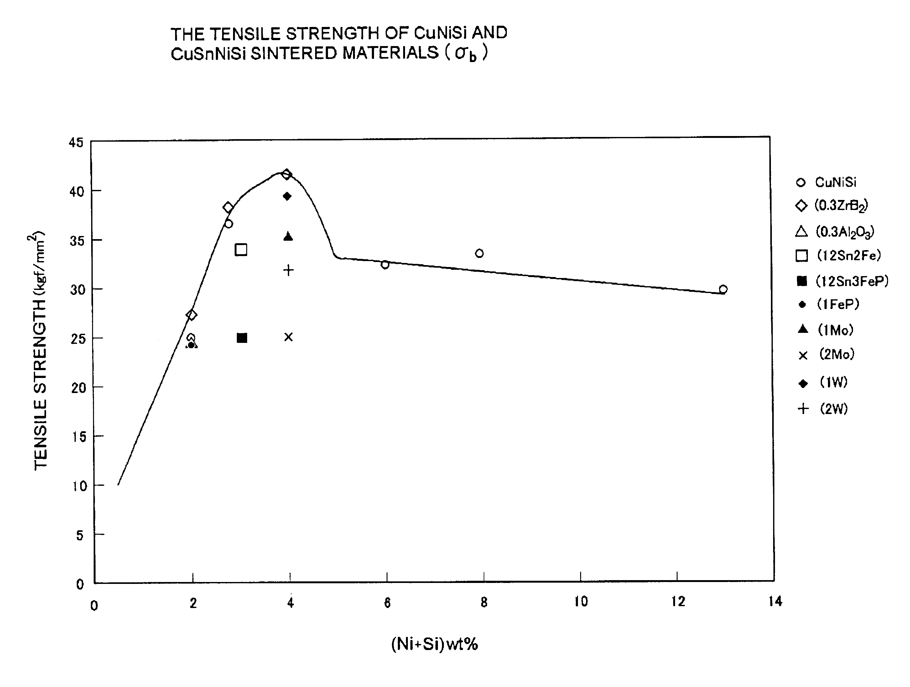
The mixed powders shown in TABLE 4 were prepared using an electrolytic Cu powder (CE25, CE15); Si, TiH powders of #300 mesh or less; phosphor iron (Fe 25 wt % P); NiAl3; Ni, Fe powders having an average particle diameter of 5 μm; an Fe 48 wt % Co powder having an average particle diameter of 9.8 μm; an SiO2 powder having an average diameter of 21 μm; a zircon sand (ZrO2 SiO2) powder having an average particle diameter of 23 μm; Al2O3 powders having average particle diameters of 2 μm and 24 μm, respectively; a ZrB2 powder having an average particle diameter of 1 μm; a W, Mo, TiN powder; an MnS powder having an average particle diameter of 1.2 μm; and an artificial graphite (SGO) powder having an average particle diameter of 50 μm. These mixed powders were pressed at a compacting pressure of 2 to 5 ton / cm2, thereby forming green compacts. The green compacts thus formed were respectively sintered in an atmosphere of Ax gas (ammonia cracked gas) having a dew point of 35° C. or less. It ...

example 2

This example is associated with an investigation conducted on Cu—Sn bronze based sintered contact materials to which lead is added in amounts up to 3 wt %. The sintered contact materials used in this example were produced in the following way: The mixed powders shown in TABLE 6 were prepared using, in addition to the raw powder materials used in Example 1, Sn, Pb, Al, cemented carbide and Cu—30 wt % Zn which have a size of #250-mesh or less and Cr, Mn, MnSi, TiSi which have a size of #300-mesh or less. These powders were compacted at a compacting pressure of 2 ton / cm2 to form green compacts and then, the green compacts were respectively sintered in an atmosphere of AX gas (ammonia cracked gas) having a dew point of 35° C. or less. The sintering temperature varied depending on the compositions of the materials but ranged from 850 to 900° C. The sliding properties (PV value, ΔW) evaluated in the same way as in Example 1 are shown in TABLE 6.

TABLE 6CEMENTEDPVNo.CE15SnPbFePTiHNiSiAlZnSi...

example 3

This example is associated an investigation conducted on bronze based and lead bronze based sintered contact materials to which lead is added in amounts up to 25 wt %. The sintered contact materials used in this example were produced in the following way: The mixed powders shown in TABLES 7 and 8 were prepared using, in addition to the raw powder materials used in Example 1 and Example 2, KJ4 (25 wt % P—Cu alloy) of #250-mesh or less. These powders were compacted at a compacting pressure of 2 ton / cm2 to form green compacts and then, the green compacts were respectively sintered in an atmosphere of AX gas (ammonia cracked gas) having a dew point of 35° C. or less. The sintering temperature varied depending on the compositions of the materials but ranged from 800 to 860° C.

TABLE 7CE153.18 gr / cm3No.CuSnPbTiHNiSiSiO2FePMoWNiAl3FeCoCaF2PV VALUEΔ WmmC1Bal.1110.1555000.08C2Bal.1130.1560000.06C3Bal.1150.1560000.09C4Bal.1180.1560000.13C5Bal.11100.1555000.27C6Bal.11101275000.04C7Bal.111031750...


PUM

PropertyMeasurementUnit
particle diameteraaaaaaaaaa
sizeaaaaaaaaaa

Abstract

With the objectives of alleviating the property of attacking on the mating member by scratching-off of local agglutinates on the sliding contact surface, achieving improved wear resistance, and achieving improved seizure resistance through restraint of frictional heat generation by a hard phase, a copper based sintered contact material contains shock-resistant ceramics in an amount of 0.05 to less than 0.5 wt % as non-metallic particles composed of one or more substances selected from pulverized oxides, carbides and nitrides. The shock-resistant ceramics are comprised of SiO2 and / or two or more substances selected from SiO2, Al2O3, LiO2, TiO2 and MgO.

Description

TECHNICAL FIELDThe present invention relates to a copper based sintered contact material and a double-layered sintered contact member produced by sinter-bonding the copper based sintered contact material to an iron based material.BACKGROUND OF THE INVENTIONGenerally, various copper based alloys are selected for use as a bearing material according to conditions such as oil lubricating conditions, sliding speed and sliding contact surface pressure. For bearing materials used in oil, comparatively soft bronze (e.g., BC3 and BC6), phosphor bronze (e.g., PBC2A), lead bronze (e.g., LBC 2-5) and kelmet (e.g., KJ 1-4) casting materials are utilized. In conditions a little poor in oil lubricity, Cu—Sn or Cu—Sn—Pb is used as a copper based sintered bearing material and bronzed based oil-less bearings produced by adding graphite (solid lubricant) to Cu—Sn or Cu—Sn—Pb (copper based sintered bearing material) are often used.In the roller sections of undercarriages for construction machines, doub...

Claims


Application Information

Patent Timeline
Patent Type & Authority Patents(United States)
IPC IPC(8): C22C9/08C22C32/00C22C9/06C22C9/02F16C33/04F16C33/12B22F5/00B22F7/00B22F7/06B22F7/08C22C1/05F16C33/14F16C33/24
CPCC22C9/02C22C9/08C22C32/00F16C33/043F16C33/121C22C9/06Y10T428/12903Y10S384/912Y10S384/91Y10S384/913F16C2204/10Y10T428/12917Y10T428/12535Y10T428/12063Y10T428/12576Y10T428/12611F16C2206/80F16C2204/12
Inventor TAKAYAMA, TAKEMORIOHNISHI, TETSUOTANAKA, YOSHIKIYOMAEDA, KEIICHISATO, KAN'ICHI
Owner KOMATSU LTD
Learn More