

Method for coating a metal with a ceramic coating, electrolyte used therefor, ceramic coating, and metal material
a ceramic coating and metal technology, applied in the field of methods, can solve the problems of inability to form hard coatings with improved chipping, inability to achieve sufficient corrosion resistance in surface treatment, nickel plating, etc., and achieve excellent corrosion resistance, low attack on the counter member, and high abrasion resistance
- Summary
- Abstract
- Description
- Claims
- Application Information
AI Technical Summary
Benefits of technology
Problems solved by technology
Method used
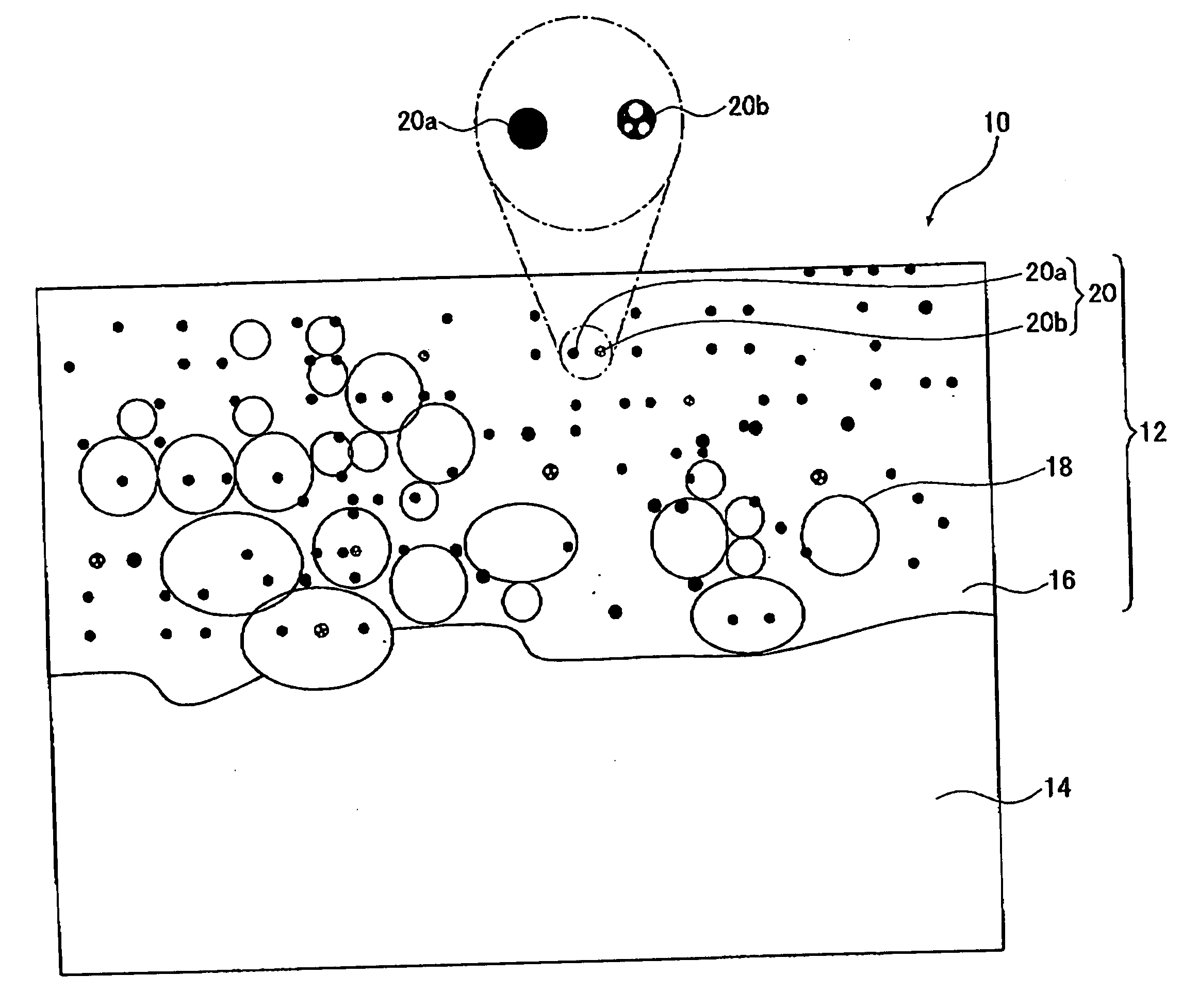
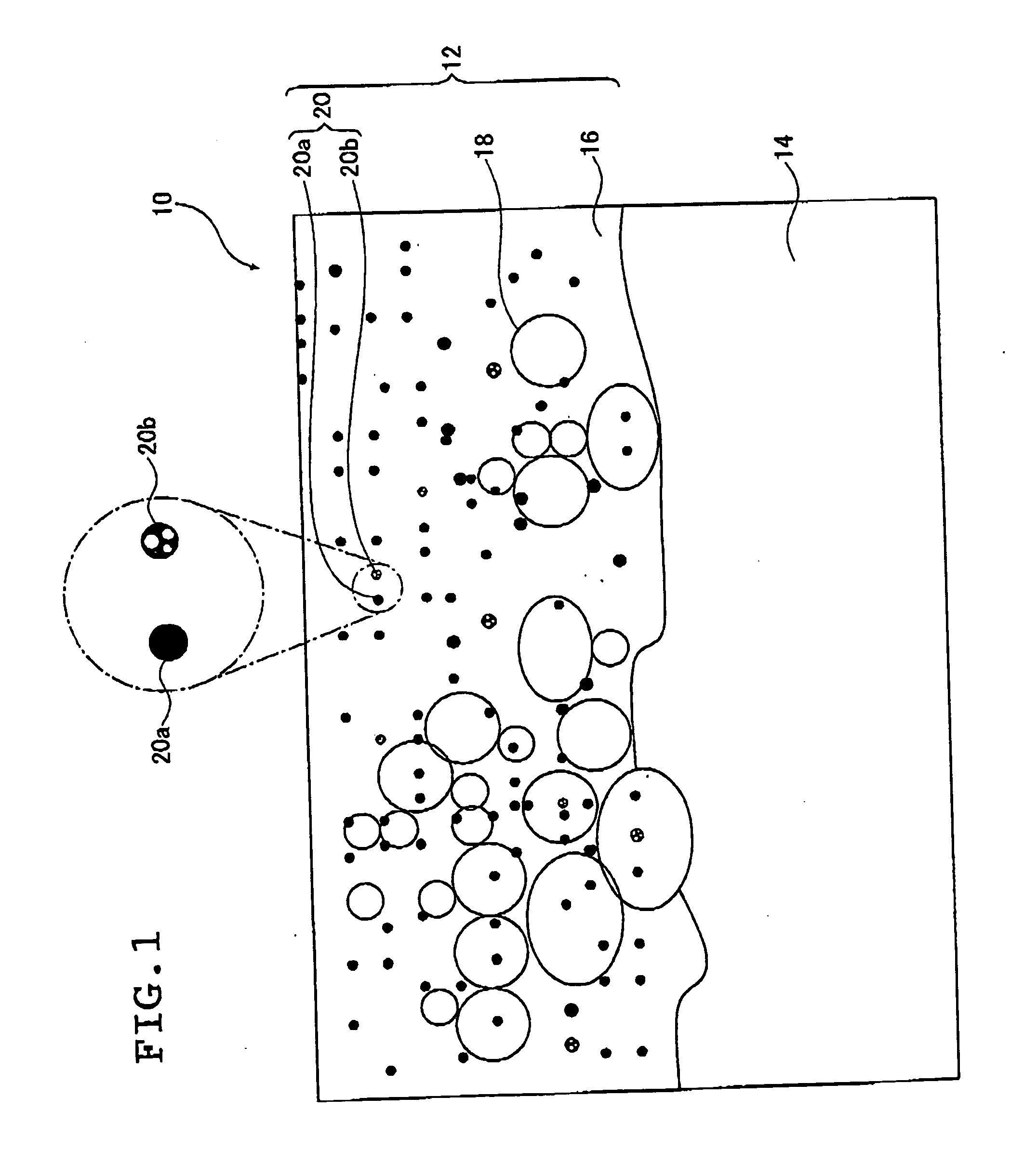
Image

Examples
example 1
[0210]Electrolysis was conducted for 10 minutes by bipolar electrolysis using a magnesium die cast alloy plate (a plate of JIS AZ91D series) having a surface area of 1 dm2 for the working electrode and a stainless steel plate for the counter electrode to form a coating on the magnesium die cast alloy plate. When the surface of the working electrode was observed during the electrolysis, light emission by glow discharge and arc discharge was observed.
[0211]The electrolyte used was the one prepared by adding 8.6 g / L of ammonium dihydrogenphosphate and 1.2 g / L (in terms of zirconium oxide) of zirconium oxide particles (a zirconium oxide sol dispersed in water manufactured by Daiichi Kigenso Kagaku Kogyo Co., Ltd. having an average particle size of 0.07 μm, monoclinic crystal) to water, and adjusting the pH to 12.8 by using ammonia solution and potassium hydroxide.
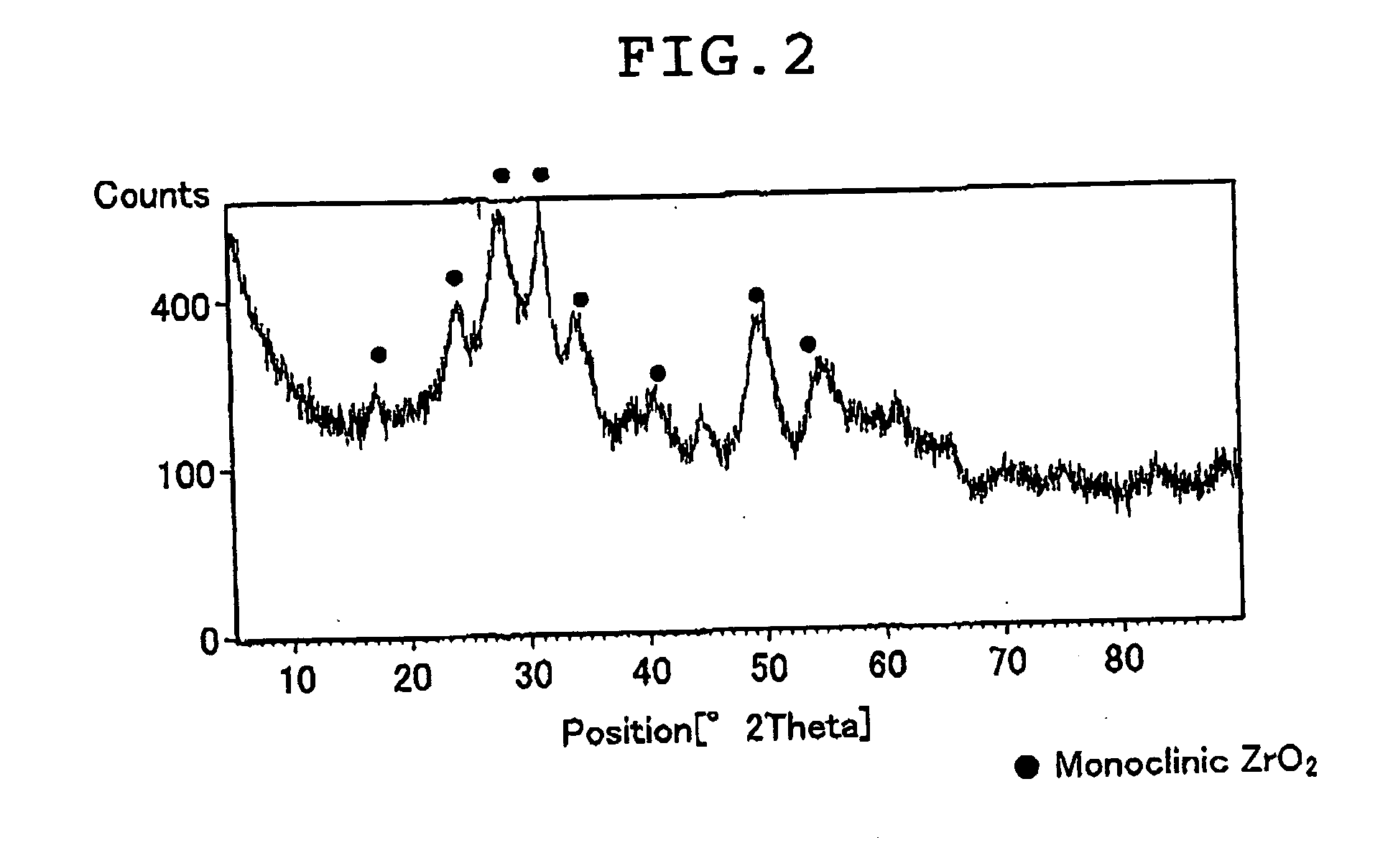
[0212]The zirconium oxide sol dispersed in water used in the electrolyte was collected on a filter paper, and the zirconium o...
example 2
[0215]Electrolysis was conducted for 10 minutes by bipolar electrolysis using a magnesium die cast alloy plate (a plate of JIS AZ91D series) having a surface area of 1 dm2 for the working electrode and a stainless steel plate for the counter electrode to form a coating on the magnesium die cast alloy plate. When the surface of the working electrode was observed during the electrolysis, light emission by glow discharge and arc discharge was observed.
[0216]The electrolyte used was the one prepared by adding 8.6 g / L of ammonium dihydrogenphosphate and 6 g / L (in terms of zirconium oxide) of zirconium oxide particles (a zirconium oxide sol dispersed in water manufactured by Daiichi Kigenso Kagaku Kogyo Co., Ltd., having an average particle size of 0.07 μm; monoclinic crystal) to water, and adjusting the pH to 12.7 by using ammonia solution and sodium hydroxide.
[0217]The electrolyte had an electric conductivity of 1.8 S / m, and a ζ potential of −25 mV.
[0218]The waveform used was the same a...
example 3
[0219]Electrolysis was conducted for 5 minutes by unipolar electrolysis using a magnesium die cast alloy plate (a plate of JIS AZ31D series) having a surface area of 1 dm2 for the working electrode and a stainless steel plate for the counter electrode to form a coating on the magnesium die cast alloy plate. When the surface of the working electrode was observed during the electrolysis, light emission by glow discharge and arc discharge was observed.
[0220]The electrolyte used was the one prepared by adding 6 g / L (in terms of zirconium oxide) of zirconium oxide particles (a zirconium oxide sol dispersed in water manufactured by Daiichi Kigenso Kagaku Kogyo Co., Ltd. having an average particle size of 0.07 μm; monoclinic crystal) to water, and adjusting the pH to 12.5 by using ammonia and lithium hydroxide.
[0221]The electrolyte had an electric conductivity of 1.85 S / m, and a ζ potential of −27 mV.
[0222]A pulse wave having a sinusoidal waveform with a positive peak value of 600 V (maxim...
PUM
| Property | Measurement | Unit |
|---|---|---|
| particle size | aaaaa | aaaaa |
| electric conductivity | aaaaa | aaaaa |
| ζ potential | aaaaa | aaaaa |
Abstract
Description
Claims
Application Information