Electrical machines, especially engines excited by permanent magnets

a technology of permanent magnets and electric machines, which is applied in the direction of dynamo-electric machines, magnetic circuit rotating parts, magnetic circuit shape/form/construction, etc., can solve the problems of requiring special magnetizing devices for magnetization, negative effect on machine output, and possible requirement of larger rotor diameters than would be necessary for machine output, etc., to prevent dangerous bending stresses, simple and rugged structural design of the rotor

Inactive Publication Date: 2006-04-18
ROBERT BOSCH GMBH
View PDF7 Cites 52 Cited by
  • Summary
  • Abstract
  • Description
  • Claims
  • Application Information

AI Technical Summary

Benefits of technology

[0009]The electrical machine according to the invention, has the advantage over the prior art that by dividing up the magnet rings of the rotor into individual magnets, these can be simply manufactured in a dimensionally accurate manner and can be magnetized with consistent strength as north poles or south poles. Another advantage lies in the fact that the individual magnets can easily be mounted on the rotor circumference without internal stress and can be precisely positioned. In addition, environmentally hazardous additives such as glues or casting resins can be eliminated. An additional significant advantage is that receiving the axial ends of the individual magnets in frames on both sides allows the manufacturing tolerances of the permanent magnets and of the support to be compensated for through an axial clamping.
[0013]In order to prevent dangerous bending stresses in the permanent magnets, they are independently clamped in place with a uniform force in that at least the frame at one of the axial ends of the permanent magnets is provided with slits extending radially inward between each pair of adjoining recesses. It is thus possible for the slits to divide the frame into radially outward pointing, axially resilient segments, each of which is provided with one of the recesses on its end surface oriented toward the permanent magnets; an axial end of one of the permanent magnets is clamped into each recess with a wedging force generated by the axially resilient prestressed segments. For a simple production and assembly and a rugged embodiment of the frame disposed at the other axial ends of the permanent magnets, this frame is embodied as a slit-free annular frame whose recesses on the end surfaces each receive an axial end of one of the permanent magnets in a positively engaging manner.
[0015]When the rotor design according to the invention is used in transverse flux machines, the permanent magnets preferably constitute at least two annular arrangements, which are spaced apart from each other by a fixed axial distance. The distance of the two annular arrangements from each other is suitably predetermined by a common, slit-free annular frame, both of whose end surfaces are provided with recesses, each for receiving a respective axial end of the permanent magnets in a positively engaging manner. Both when the permanent magnets are arranged in two rings and when they are arranged in multiple rings, it is suitable for only the frames disposed on the two end surfaces of the rotor to be provided with radial slits and axially resilient segments. A simple and rugged structural design of the rotor is produced by placing the permanent magnets and the annular frames onto a common support and attaching them there. The support here is suitably embodied as a magnetic yoke ring for the permanent magnets.

Problems solved by technology

This has the disadvantage of requiring a special magnetizing device for the magnetization.
In addition, the transitions of the alternating polarities along the rotor surface are imprecise due to this kind of magnetization, which has a negative effect on the machine output.
In addition, with magnetizing devices of this kind, the individual permanent magnets cannot be embodied with an arbitrarily narrow width so that with a predetermined number of poles, it is possible that larger rotor diameters will be required than would be necessary for the machine output.
In other designs of the rotor in which prefabricated tube sections made of magnetic material with premagnetized poles are slid onto the rotor and affixed, there is also, due to the brittleness of the material, the danger of material fractures due to internal stress after the magnet rings are placed onto the rotor.

Method used


Image

  • Electrical machines, especially engines excited by permanent magnets
  • Electrical machines, especially engines excited by permanent magnets
  • Electrical machines, especially engines excited by permanent magnets

Examples


Embodiment Construction

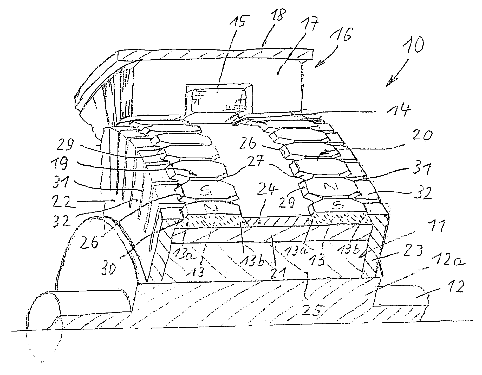
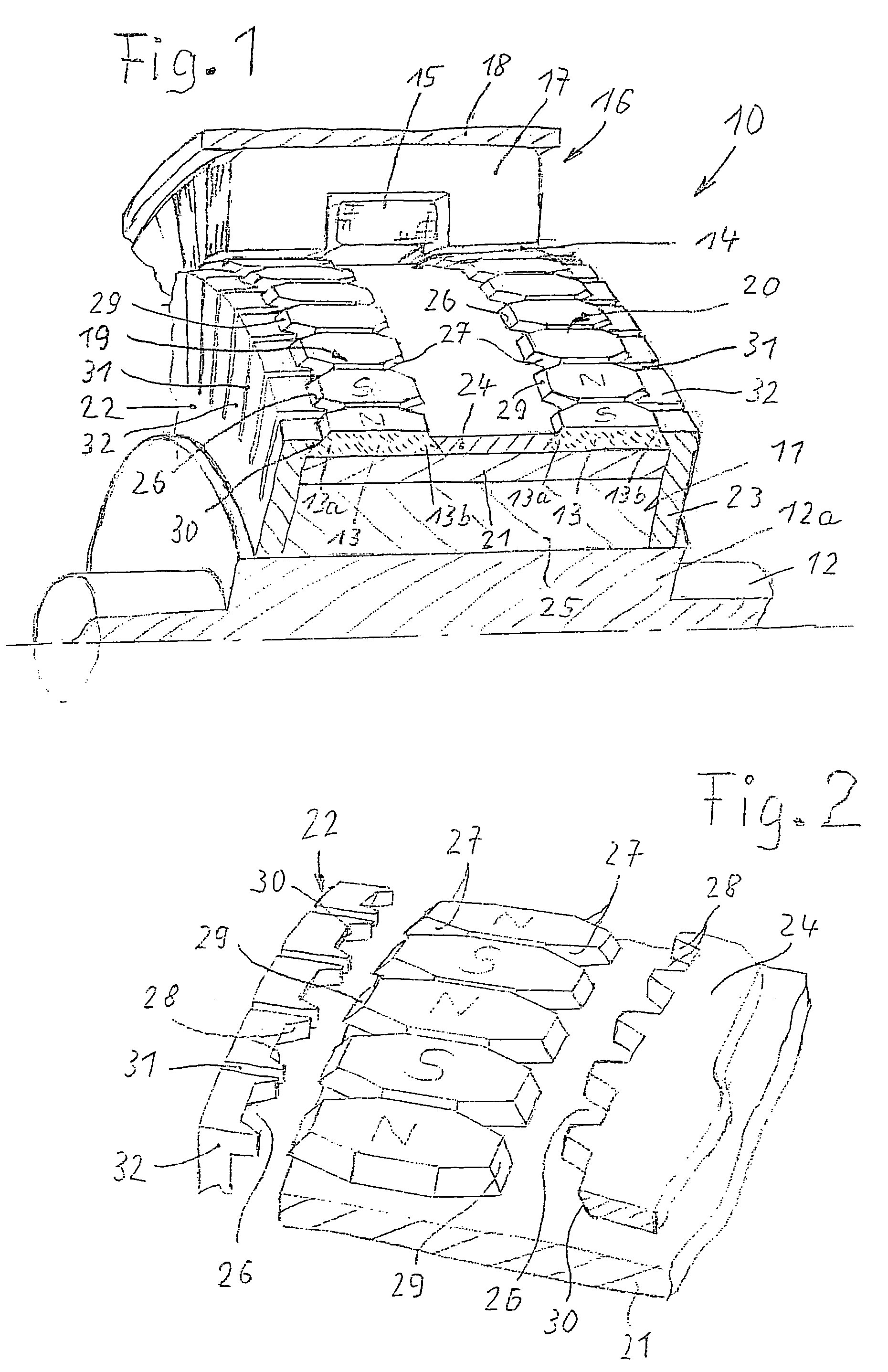
[0020]In a longitudinal section that extends to the depth of the central axis, FIG. 1 shows a perspective breakaway view of an electrical machine 10 that belongs to the subgroup of transverse flux motors. The machine has a rotating rotor 11 with a rotor shaft 12. A number of permanent magnets 13 with alternating polarities are disposed around its circumference and the permanent magnets 13 are magnetized in the radial direction. The permanent magnets 13 cooperate across a working air gap 14 with an electrical annular coil 15 of a stator 16, which concentrically encompasses the rotor 11 and whose lamination bundles 17 on the one hand, are disposed opposite the permanent magnets 13 and on the other hand, encompass the annular coil 15 in a U-shape. The stator lamination bundles and annular coils are held and positioned by means of a corresponding yoke housing 18.

[0021]The permanent magnets 13 are arranged in two annular arrangements 19, 20 made up of individual magnets disposed next to ...


PUM


Abstract

A permanent magnet-excited electric motor with a rotating rotor having permanent magnets disposed with alternating polarities in a ring around its circumference, which magnets cooperate with coils of a stator encompassing the rotor. The permanent magnets, as individual magnets next to one another that are distributed uniformly over the circumference of the rotor, rest on an annular support and are clamped in place at their axial ends by a respective annular frame made of magnetically inactive material.

Description

CROSS-REFERENCE TO RELATED APPLICATIONS[0001]This application is a 35 USC 371 application of PCT / DE 03 / 00236 filed on Jan. 29, 2003.BACKGROUND OF THE INVENTION[0002]1. Field of the invention[0003]The invention relates to an improved electrical machine, in particular a permanent magnet-excited motor with a rotating rotor.[0004]2. Description of the Prior Art[0005]Electrical machines that function as motors or generators include subgroups whose rotors have permanent magnets that constitute poles with alternating polarities along the circumference of the rotor and as a rule cooperate with electrical coils of a stator concentrically encompassing the rotor. The electrical coils of the stator generate a rotating field that carries the rotor along with it at a synchronous speed. Depending on the activation of the stator coils, these machines can also be used as so-called stepping motors, which can be exactly set to predetermined positions, for example in order to drive actuators. A subgrou...

Claims


Application Information

Patent Timeline
Patent Type & Authority Patents(United States)
IPC IPC(8): H02K21/12H02K1/27H02K21/14
CPCH02K21/145H02K1/278H02K1/28H02K1/27
Inventor DOMMSCH, HANS-PETERKASTINGER, GUENTER
Owner ROBERT BOSCH GMBH
Why Eureka
Try Eureka