
System and method for retrofit mechanism for motorizing a manual turret

a technology of retrofit mechanism and manual turret, which is applied in the direction of ignition automatic control, dynamo-electric converter control, instruments, etc., can solve the problems of slewing the turret out of control, and affecting the operation of manual slewing

Inactive Publication Date: 2006-04-18
UNITED STATES OF AMERICA THE AS REPRESENTED BY THE SEC OF THE ARMY
View PDF19 Cites 40 Cited by
  • Summary
  • Abstract
  • Description
  • Claims
  • Application Information

AI Technical Summary

Benefits of technology

[0015]Accordingly, the present invention may provide an improved system and method for a retrofit motorized turret that may overcome deficiencies of conventional approaches.

Problems solved by technology

When the weight of the turret mechanism is increased (e.g., when additional equipment is added to the devices already on the turret assembly) beyond certain limits, the manual slewing operation of the turret becomes too difficult for a person of normal stature (e.g., a person in a 50th percentile) to accomplish in a practical manner.
Without the hand crank assembly assistance, and sometimes due to high stresses involved, overcompensation (e.g., slewing past a desired target zone) and operator fatigue can, at the extreme, lead to slewing the turret out of control.
Such a situation is obviously hazardous when, for example, the operator is attempting to maneuver a turret mounted weapon into firing position, especially when the vehicle where the turret is installed is on an incline that adds additional gravitational forces that must overcome.
However, even implementation of a hand crank assembly has deficiencies in that for proper ergonometric considerations, the gear reduction is such that the hand crank can be operated by a 5th percentile female soldier which generally slows the slewing operation considerably, the hand crank assembly is incorporated in connection with a hand brake which must be released before the turret can be slewed and reset after the turret is slewed which also slows the slewing operation as well as causing a distraction, the hand crank assembly adversely encroaches on a 95th percentile male gunner envelope thus causing a reduction in space and mobility for such a gunner, and the crank assembly protrudes such that the gunner or equipment can bump or snag on the crank assembly.
However, such assemblies are generally expensive (costly), prone to increase electrical path resistance and loss of electrical continuity due to damage and corrosion, require area on the turret and mount when the amount of desired area may already be limited, require extensive modification to a structure such as the turret and the turret mounting that was not initially designed for a motorized assembly, etc.
Such an approach has the deficiency of limiting the useful angular range of the vehicle where the turret is mounted.
Such turret rotation angular limitations are generally unacceptable for military vehicles.
The conventional slip ring or multi-geared ring and contactor assemblies, and the conventional direct hard wiring approaches may also tax limited vehicle electrical power capacity.
Such a placement can cause the turret to be unbalanced (i.e., the center of gravity of the turret may be significantly skewed from the axis of rotation of the turret).
However, such conventional approaches have deficiencies that include the addition of cost and weight, restriction of operator movement, and reduction of usable space.

Method used


Image

  • System and method for retrofit mechanism for motorizing a manual turret
  • System and method for retrofit mechanism for motorizing a manual turret
  • System and method for retrofit mechanism for motorizing a manual turret

Examples


Embodiment Construction

)

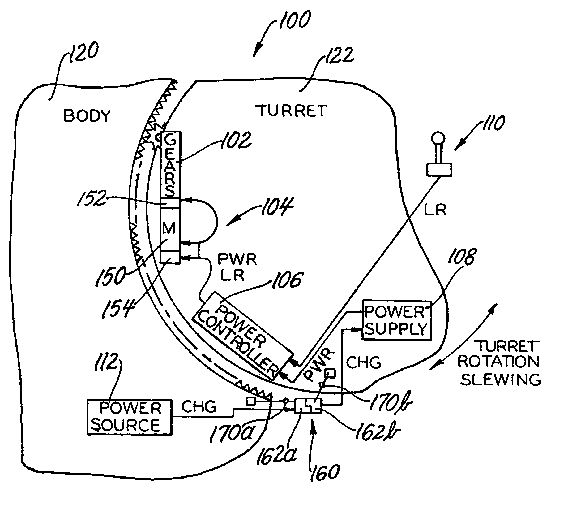
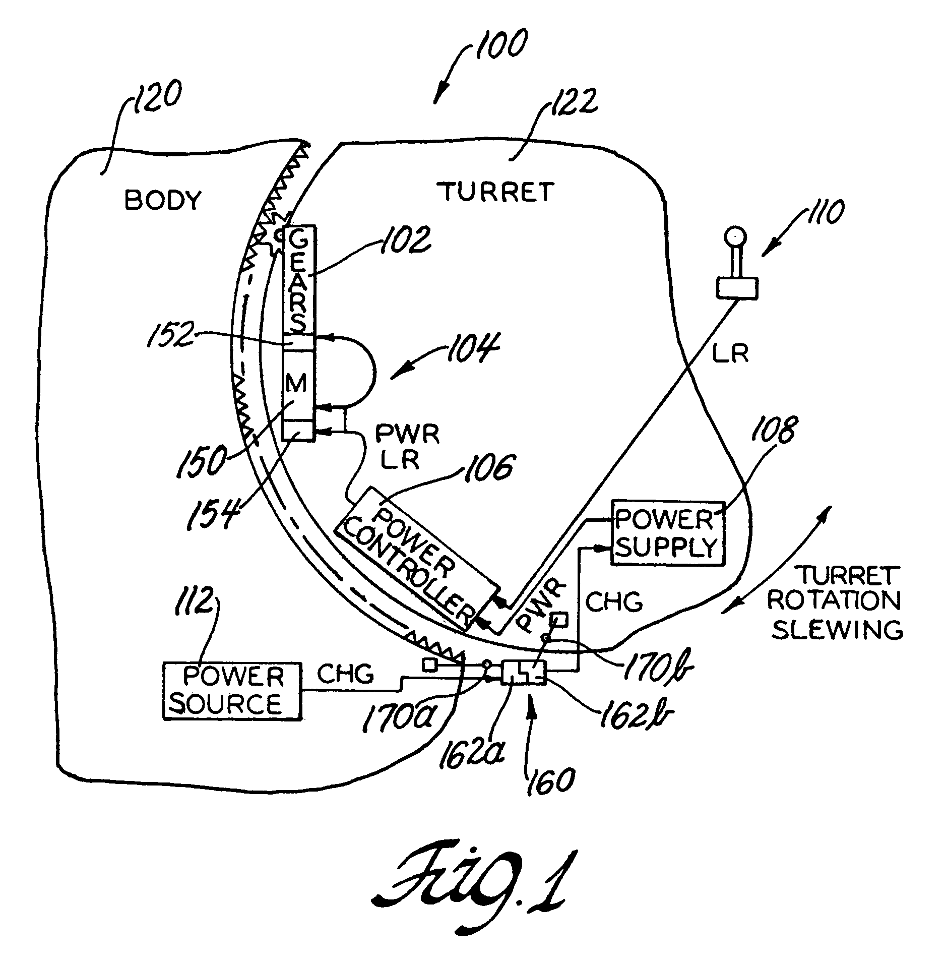
[0021]With reference to the Figures, the preferred embodiments of the present invention will now be described in detail. Generally, the present invention provides an improved mechanism (i.e., system, apparatus, kit, assembly, etc.) and an improved method (i.e., operation, process, steps, procedure, etc.) for a retrofit (i.e., aftermarket, post-typical assembly, etc.) motorized turret. The present invention may be implemented in lieu of an existing manually operated, hand cranked turret rotating assembly. The present invention may be implemented when there is no existing assistance or aid to rotation of the turret assembly.

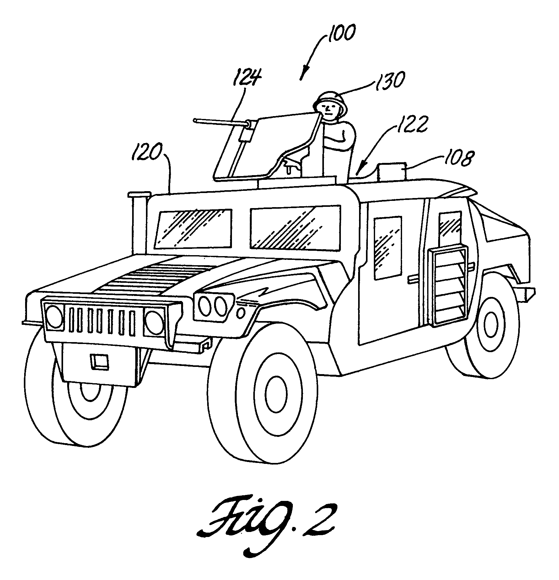
[0022]In one example, the present invention may be advantageously implemented in connection with an M-1114 High Mobility Multipurpose Wheeled Vehicle (HMMWV), turret assembly. However, the present invention may be implemented in connection with any appropriate turret mechanism in vehicle and non-vehicle (e.g., watercraft, land-based installations, aircraft, etc.) ...


PUM


Abstract

A mechanism for retrofitting a turret that has a manual rotation system with a motorized turret rotation system includes a gear box mechanically coupled to the turret, an electrically powered prime mover unit mechanically coupled to the gear box, a user operated control device electrically coupled to the prime mover unit, and an electrical power supply electrically coupled to the prime mover unit. The turret rotates relative to a body structure. The gear box and the prime mover unit are mounted to the body structure. The control device and the electrical power supply are positioned on the turret. The power supply provides electrical power to the prime mover. The control device presents a control signal to the prime mover when the user actuates the control device, and the turret rotates in response to the control signal.

Description

GOVERNMENT INTEREST[0001]The invention described here may be made, used and licensed by and for the U.S. Government for governmental purposes without paying royalty to us.BACKGROUND OF THE INVENTION[0002]1. Field of the Invention[0003]The present invention generally relates to a system and method for a retrofit mechanism for motorizing a manual turret.[0004]2. Background Art[0005]Many military vehicle vehicles (e.g., an M-1114 High Mobility Multipurpose Wheeled Vehicle, HMMWV) have a turret assembly mounted on a relatively stationary section (e.g., vehicle body). Such turret mechanisms often include weaponry (e.g., machine guns, rocket launchers, and the like), boom assemblies, audio equipment, nozzles, etc. as well as such assemblies as attack protective equipment, weather protective equipment, operation devices, etc. The turret assembly on many of such vehicles is normally manually slewed (i.e., traversed, rotated, moved about a normally vertical axis, laterally aimed, rotationall...

Claims


Application Information

Patent Timeline
IPC IPC(8): H02P1/00
CPCF41A23/24F41A27/00
Inventor SCHMITZ, JOHN J.PETROVICH, PAUL A.STORMER, A. DAVIDWASHBURN, ROBERT G.
Owner UNITED STATES OF AMERICA THE AS REPRESENTED BY THE SEC OF THE ARMY
Learn More