Real-time method and apparatus for tracking a moving object experiencing a change in direction

a technology of moving objects and real-time tracking, applied in the direction of instruments, television systems, color signal processing circuits, etc., can solve the problems of inconvenient use of high-speed camera approaches, inability to record exact location where the ball hits the ground, and inability to use such techniques. to achieve accurate ball trajectory and accurate position of ball boun

Inactive Publication Date: 2006-04-18
LUCENT TECH INC
View PDF8 Cites 25 Cited by
  • Summary
  • Abstract
  • Description
  • Claims
  • Application Information

AI Technical Summary

Benefits of technology

[0012]In combination with video camera based ball tracking methods, such as, for example, the method of Carlbom et al. described above, the acoustic and / or elastic wave analysis of the present invention illustratively allows for the tracking of a tennis ball in continuous play with volleys and ground strokes. The position of the ball at racket impact may advantageously act as a starting position for the illustrative video camera based tracking process in each direction, and / or may act as an initial starting position for the beginning of the overall tracking process (e.g., in response to a serve). The position of the ball at ground impact may advantageously provide an accurate position for the ball bounce, thereby resulting in an accurate ball trajectory, and / or may act as a terminating position for the tracking process (e.g., when the ball lands outside the appropriate court boundaries).

Problems solved by technology

Unfortunately, the very high speed camera approach used is not suitable for continuous tracking applications because these cameras provide a very narrow field of view and are very costly—thus, practical considerations (e.g., number of required cameras and the associated cost) restrict the use of such a technique to limited applications such as line calling.
Furthermore, since the video cameras sample the environment at discrete time intervals, the exact location where the ball hits the ground may not be recorded even when the ball is fully visible from the ball tracking cameras.
Current methods typically calculate the point of ball impact by extrapolating the calculated ball trajectory to intersect the ground plane, leading to substantial inaccuracy in the determination of the exact ball landing position.
As a result of the above, current tennis ball tracking systems are essentially limited to tracking the ball of a serve, and cannot adequately continue tracking the ball without the determination of the exact time of when and / or position of where the ball changes direction whenever it, in fact, does so.

Method used


Image

  • Real-time method and apparatus for tracking a moving object experiencing a change in direction
  • Real-time method and apparatus for tracking a moving object experiencing a change in direction
  • Real-time method and apparatus for tracking a moving object experiencing a change in direction

Examples


Embodiment Construction

An Illustrative Embodiment for Determining where the Racket Hits the Ball

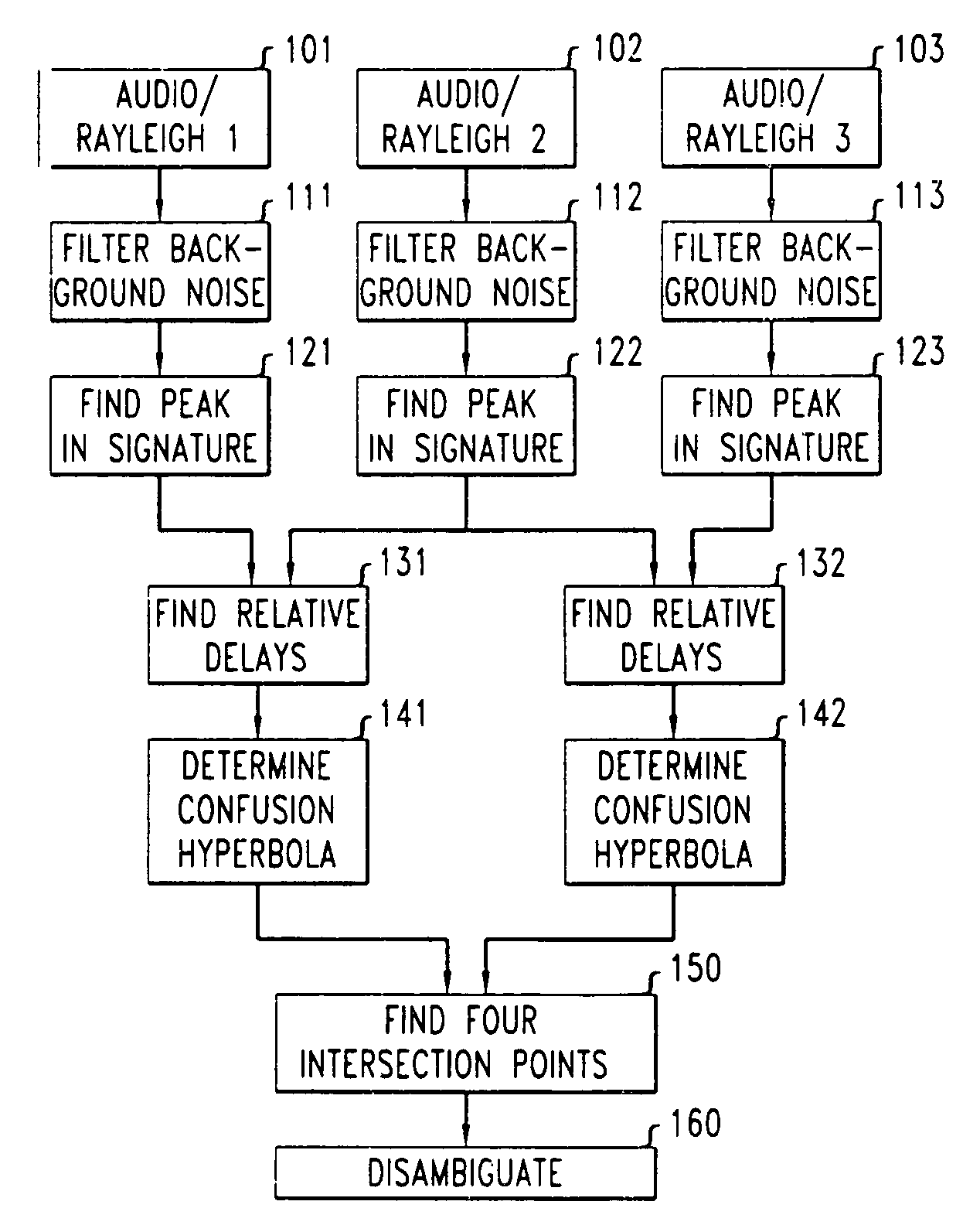
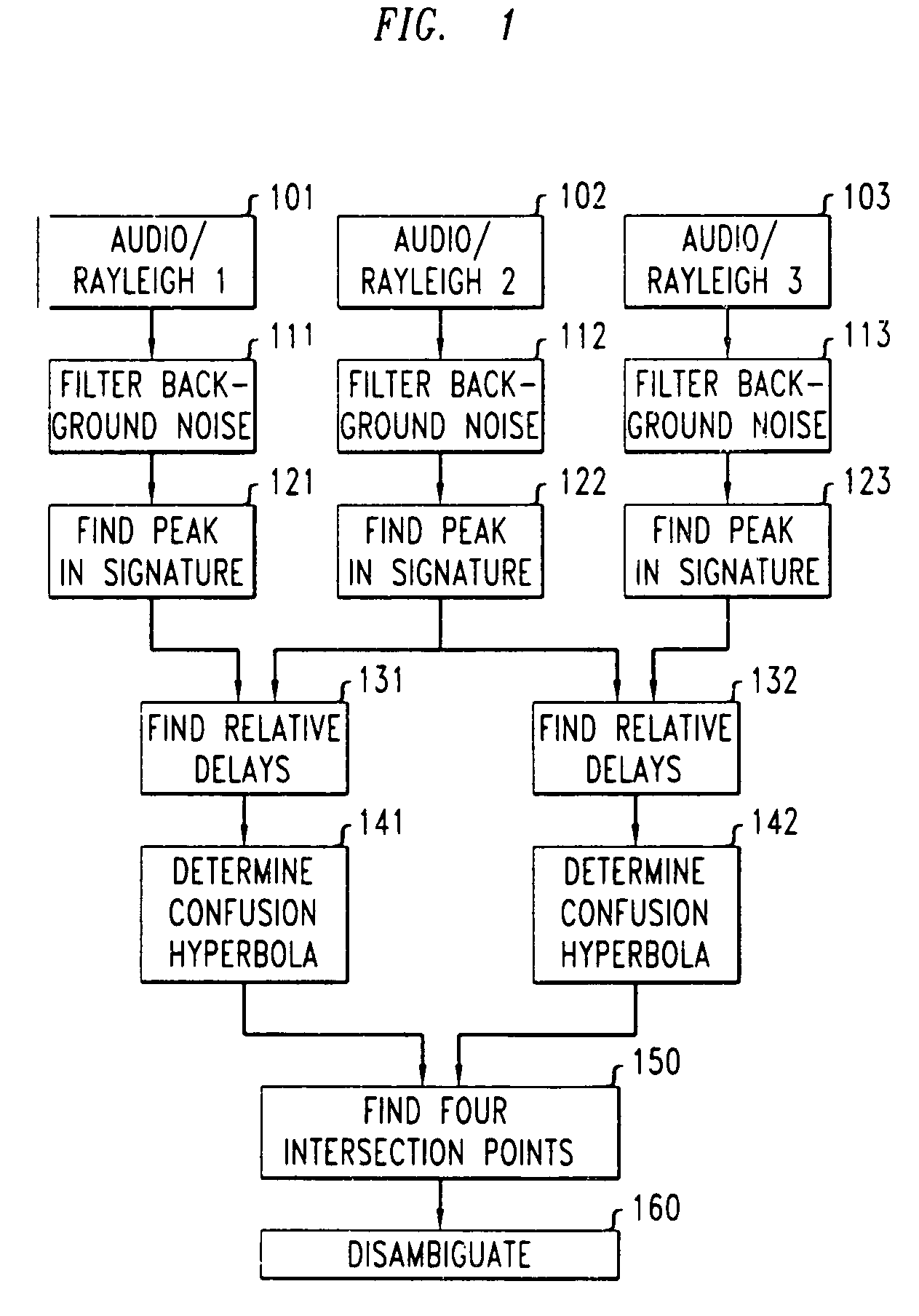
[0020]The impact of a tennis racket hitting a tennis ball (the acoustic source) generates an acoustic wave with a well defined peak and with a signature quite distinct from the ambient background noise. For example, the technique of adaptive impulse detection, well known to those skilled in the art, may be advantageously used to identify the particular type of acoustic signature created by the impact of the a tennis racket hitting a tennis ball.

[0021]In particular (and as will also be clear to those of skill in the art), various adaptation criteria may be advantageously employed, such as, for example, a threshold for background noise removal; the duration between successive impulses; frequency characteristics of the acoustic signature of the a ball hitting different court surfaces; frequency characteristics of the acoustic signature of a ball hitting a racket; frequency characteristics of the acoustic signature...


PUM


Abstract

A method and apparatus for tracking an object using one or more video cameras together with a plurality of microphones and / or geophones, whereby accurate tracking of the object can be obtained even when the object changes directions as a result of an impact. A tennis ball may be tracked during a tennis match. Prior to and after an impact, the ball is tracked with the use of video cameras, illustratively in accordance with the method disclosed in U.S. Pat. No. 6,233,007. Then, the position of the ball at racket or ground impact is accurately determined by measuring the acoustical waves generated by the ball hitting the racket and / or either the acoustic waves or the elastic (Rayleigh) waves generated by the ball hitting the ground, respectively. Tracking then advantageously continues with use of the video cameras.

Description

FIELD OF THE INVENTION[0001]The present invention relates generally to a method and apparatus for performing real-time tracking of moving objects, such as, for example, balls, pucks, and the like, in connection with sporting events, whereby trajectories corresponding to the movement of the objects are determined and such trajectory information may be used to derive information corresponding to the movement and location of the objects being tracked. More particularly, the present invention relates to a method and apparatus for the tracking of an object such as a tennis ball when the trajectory of the object experiences a sudden change in direction.BACKGROUND OF THE INVENTION[0002]One field in which real time tracking of object motion can be advantageously employed, but is not currently greatly utilized, is in the field of sports. For example, continuous tracking of the motion of a tennis ball during a tennis match can provide a wealth of valuable information, including, for example, ...

Claims


Application Information

Patent Timeline
Patent Type & Authority Patents(United States)
IPC IPC(8): H04N7/18A63B71/06G01S3/786G01S5/16G01S5/22G01S11/12G01S11/14G01V1/00G06T7/20
CPCA63B71/0605G01S3/7864G06T7/20G01S5/22G01S11/12G01S11/14G01V1/001G01S5/16A63B2071/0611A63B2220/806
Inventor CARLBOM, INGRID BIRGITTAOPALACH, AGATAWEST, JAMES EDWARD
Owner LUCENT TECH INC
Why Eureka
Try Eureka