Simplified TV tuner intermediate frequency circuit

a technology of intermediate frequency circuit and tv tuner, which is applied in the field of television receivers, can solve the problems of increasing loss and signal level decline, difficult to and reducing the size of intermediate frequency circuit, so as to reduce the number of components, simplify the intermediate frequency tuning circuit, and reduce the cost of intermediate frequency circuit.

Inactive Publication Date: 2006-04-18
ALPS ALPINE CO LTD
View PDF17 Cites 14 Cited by
  • Summary
  • Abstract
  • Description
  • Claims
  • Application Information

AI Technical Summary

Benefits of technology

[0014]Hence, the primary object of the present invention is to simplify the intermediate frequency tuning circuit and trap circuit which are made outsi...

Problems solved by technology

This turns on the first and second diodes 36 and 37 and causes the intermediate frequency tuning circuit 32 to operate in the same way as described above, except that, since the Q factor for the tuning circuit increases,...

Method used


Image

  • Simplified TV tuner intermediate frequency circuit
  • Simplified TV tuner intermediate frequency circuit
  • Simplified TV tuner intermediate frequency circuit

Examples


Embodiment Construction

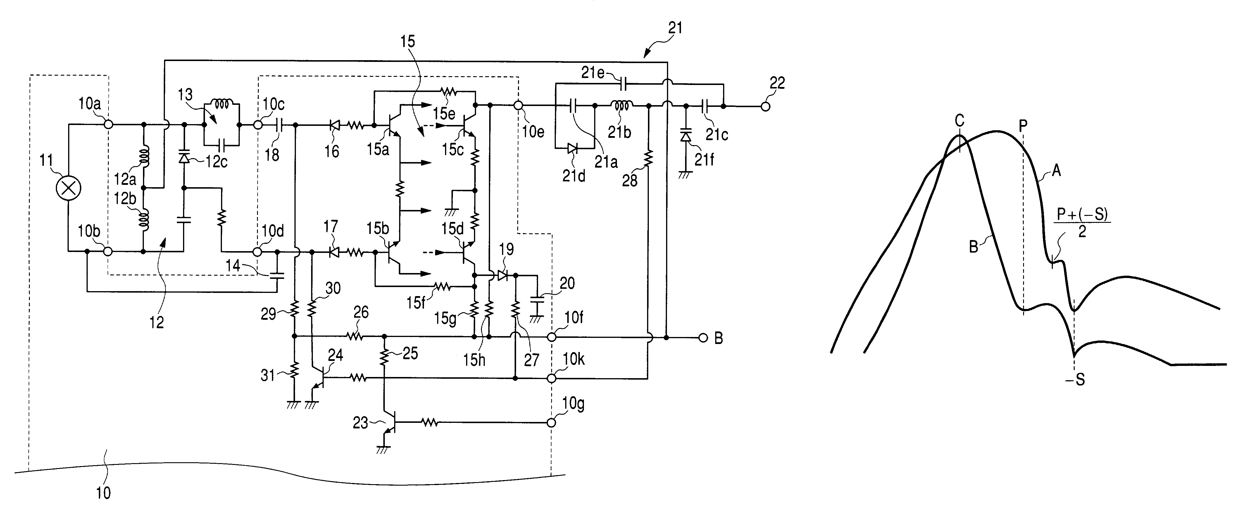
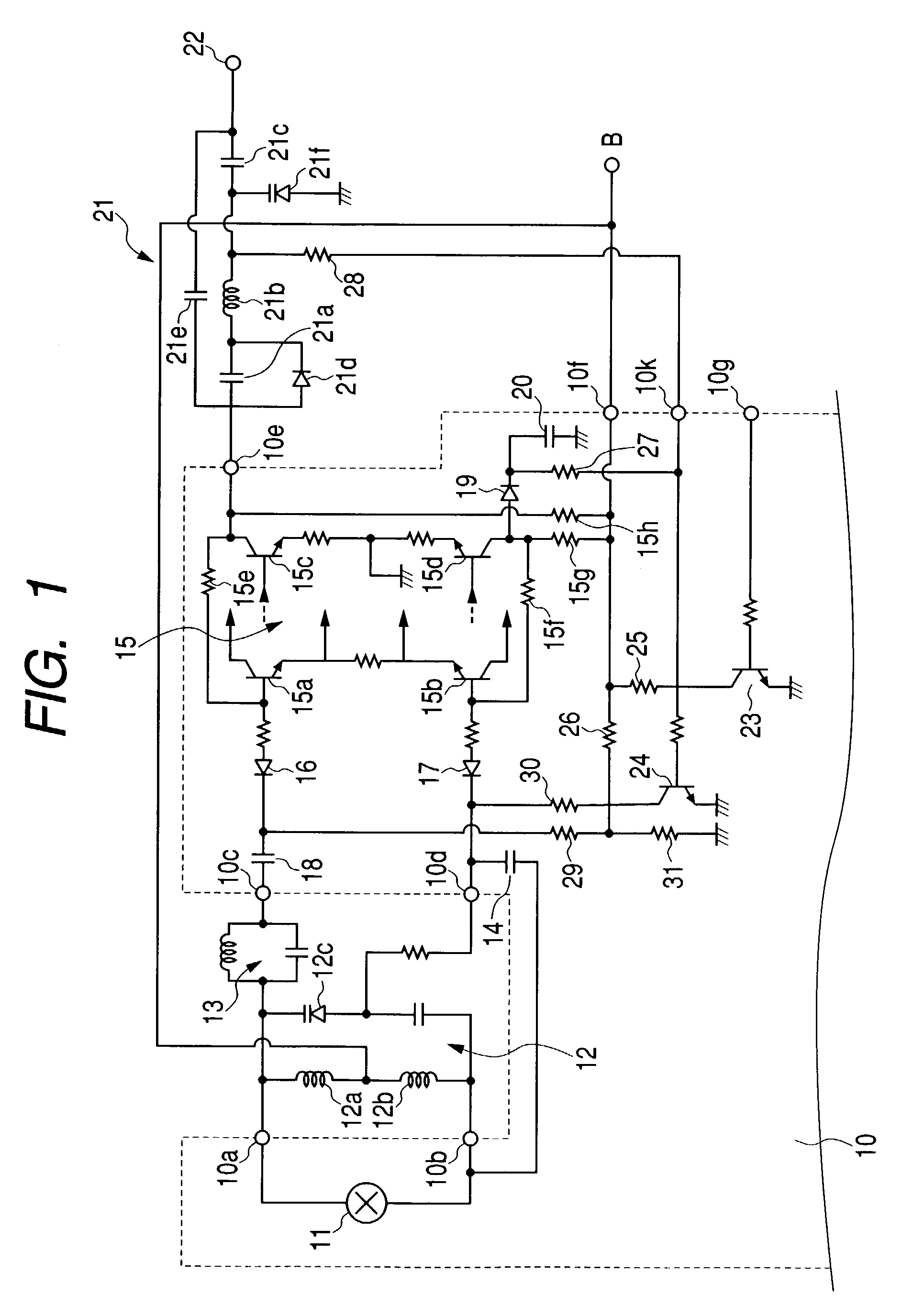
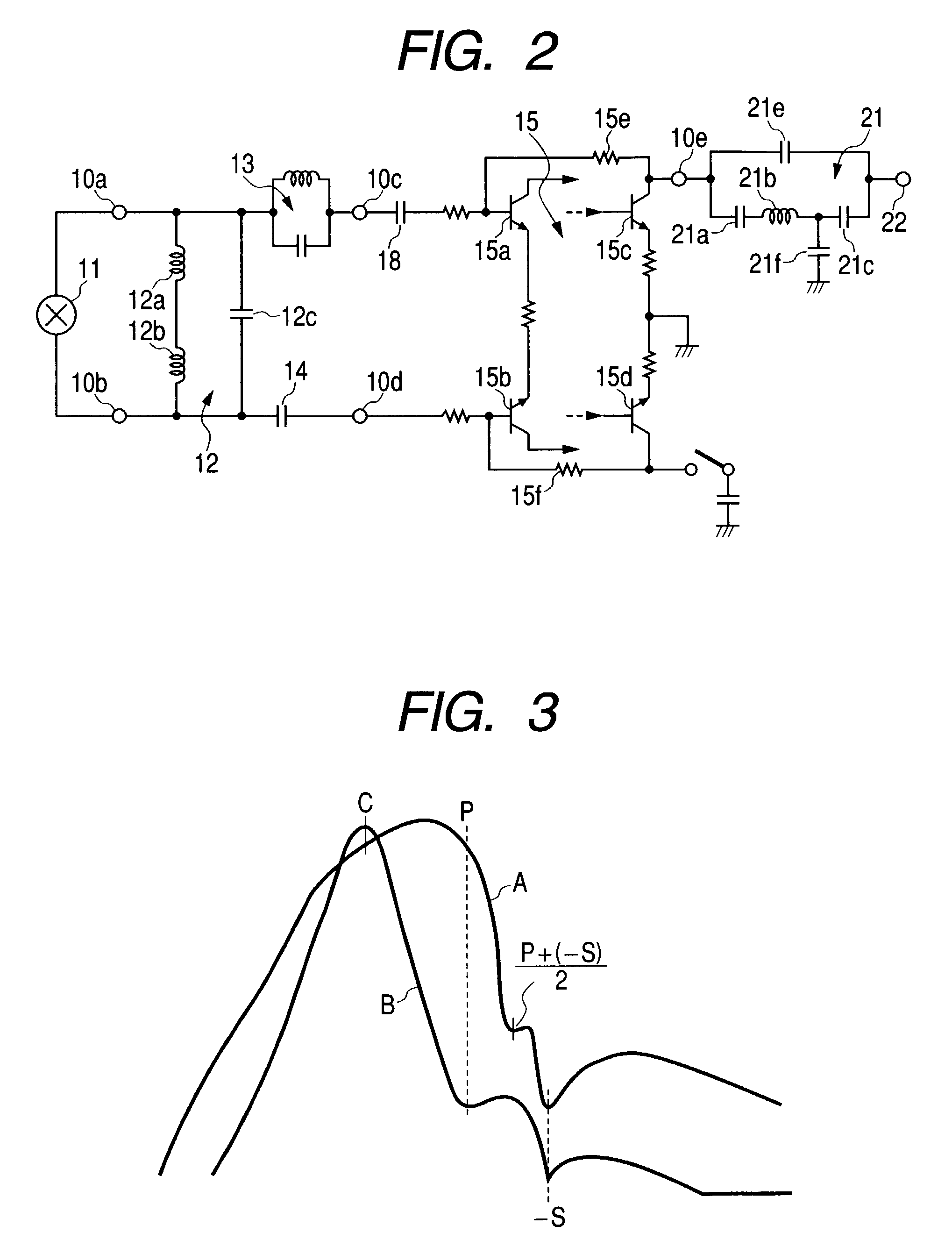
[0027]Next, the TV tuner intermediate frequency circuit according to the present invention (hereinafter simply called the “intermediate frequency circuit”) will be described referring to the accompanying drawings. FIG. 1 shows the structure of an intermediate frequency circuit according to the present invention. FIG. 2 shows an equivalent circuit for reception of a TV signal. FIG. 3 shows the transmission characteristic. FIG. 4 shows an equivalent circuit for reception of an FM broadcasting signal.

[0028]As shown in FIG. 1, a mixer 11 is incorporated in an integrated circuit 10 and there are a tuning circuit and an amplifier (not shown) outside of the integrated circuit 10. A TV signal or an FM broadcasting signal which is selected by this tuning circuit is sent to the mixer 11. Using a local oscillation signal sent from a local oscillator (not shown) located in the integrated circuit 10, the mixer 11 converts the frequency of the TV signal into a frequency in the TV intermediate fre...


PUM


Abstract

Between a mixer and an intermediate frequency amplifying circuit, there are an intermediate frequency tuning circuit which, for reception of a TV signal, is tuned between a chrominance subcarrier frequency and a video intermediate frequency in an intermediate frequency band, and for reception of an FM broadcasting signal, is tuned nearly to the chrominance subcarrier frequency, and a first trap circuit which attenuates a sound intermediate frequency of an adjacent channel. Next to the intermediate frequency amplifying circuit, there is a second trap circuit which, for reception of a TV signal, brings about attenuation between the video intermediate frequency in the intermediate frequency band and the sound intermediate frequency of the adjacent channel and, for reception of an FM broadcasting signal, brings about attenuation around the video intermediate frequency.

Description

BACKGROUND OF THE INVENTION[0001]1. Field of the Invention[0002]The present invention relates to a television receiver which can receive TV signals or FM broadcasting signals.[0003]2. Description of the Related Art[0004]The structure of a conventional television receiver is shown in FIG. 5. A mixer 31 is incorporated in an integrated circuit 30 and there are a tuning circuit, an amplifier and so on (not shown) outside of the circuit 30. A TV signal or an FM broadcasting signal which is selected by this tuning circuit is sent to the mixer 31. Using a local oscillation signal sent from a local oscillator (not shown) located in the integrated circuit 30, the mixer 31 converts the frequency of the TV signal into a frequency in the TV intermediate frequency band (54 MHz to 60 MHz in accordance with the Japanese channel specification), or the frequency of the FM broadcasting signal into a chrominance subcarrier frequency (C) in the intermediate frequency band. The frequency-converted TV s...

Claims


Application Information

Patent Timeline
IPC IPC(8): H04N5/44H04N5/46H04N5/50H03J3/20H03J5/24H04B1/26
CPCH04N5/50H04N5/4446
Inventor YAMAMOTO, MASAKI
Owner ALPS ALPINE CO LTD
Why Eureka
Try Eureka