Loss point detecting method and distributed raman amplifier applying the same

a loss point and amplifier technology, applied in the field of loss point detection and distributed raman amplifiers, can solve the problem of insufficient gain and achieve the effect of reducing the number of signal errors

Inactive Publication Date: 2006-04-18
FUJITSU LTD
View PDF8 Cites 21 Cited by
  • Summary
  • Abstract
  • Description
  • Claims
  • Application Information

AI Technical Summary

Benefits of technology

[0019]The present invention has been devised for the purpose of solving this problem, and, an object of the present invention is to provide a loss point detecting method for determining whether any loss point occurs for the purpose of avoiding a problematic situation such as a burning out of the optical transmission path material as mentioned above, and a distributed Raman amplifier which applies this method.
[0022]According to a third aspect of the present invention, a scattered-light monitoring part monitoring a scattered light separating from the optical transmission path; an excitation-light monitoring part separating a part of the excitation light and monitoring it; a reflected-light monitoring part separating a reflected light which passes in a direction opposite to the direction in which the signal light passes through the optical transmission path, and monitoring it; a determining part determining, when the power of the excitation light monitored reaches a predetermined determination value, whether or not any loss point occurs based on a ratio between the power of the scattered light monitored and the power of the reflected light monitored; and a breaking part breaking the excitation light when the determining part determines that a loss point occurs are provided. Thereby, it is possible to avoid burning out of the optical transmission path material at the loss point if any.
[0023]According to a fourth aspect of the present invention, a scattered-light monitoring part monitoring a scattered light separating from the optical transmission path; an excitation-light monitoring part separating a part of the excitation light and monitoring it; a reflected-light monitoring part separating a reflected light which passes in a direction opposite to the direction in which the signal light passes through the optical transmission path, and monitoring it; a determining part determining whether or not any loss point occurs, by increasing the power of the excitation light at a fixed rate, and comparing a time required for the power of the scattered light monitored to reach a fixed value with a time required for the power of the reflected light monitored to reach a fixed value; and a breaking part breaking the excitation light when said determining part determines that a loss point occurs are provided. Thereby, it is possible to avoid burning out of the optical transmission path material at the loss point if any.
[0024]According to a fifth aspect of the present invention, a scattered-light monitoring part monitoring a scattered light separating from the optical transmission path; an excitation-light monitoring part separating a part of the excitation light and monitoring it; a determining part determining, when the power of the excitation light monitored reaches a predetermined determination value, whether or not any loss point occurs based on the power of the scattered light monitored; and a breaking part breaking the excitation light when the determining part determines that a loss point occurs are provided. Thereby, it is possible to avoid burning out of the optical transmission path material at the loss point if any.

Problems solved by technology

However, in case the loss point occurs in the optical transmission path, a sufficient gain may not be obtained even when the excitation light power is increased accordingly.

Method used


Image

  • Loss point detecting method and distributed raman amplifier applying the same
  • Loss point detecting method and distributed raman amplifier applying the same
  • Loss point detecting method and distributed raman amplifier applying the same

Examples


first embodiment

[0040]When an excitation light is applied to an optical fiber transmission path, a scattered light and a reflected light occur other than a signal light thus amplified, as shown in FIG. 4. And when a loss point occurs in the optical fiber transmission path as mentioned above, the scattered light power ASS is small while the reflected light power Pm is large. When no loss point occurs, contrary, the scattered light power is large while the reflected light power is small. Accordingly, the present invention performs control of the excitation light power by monitoring the scattered light power and the reflected light power, and then based on the thus-monitored powers.

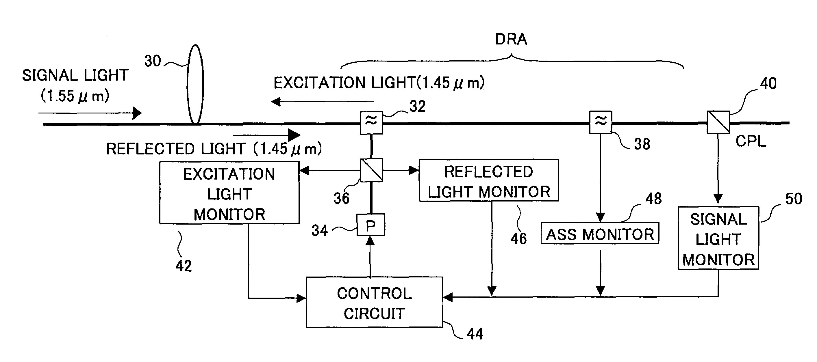
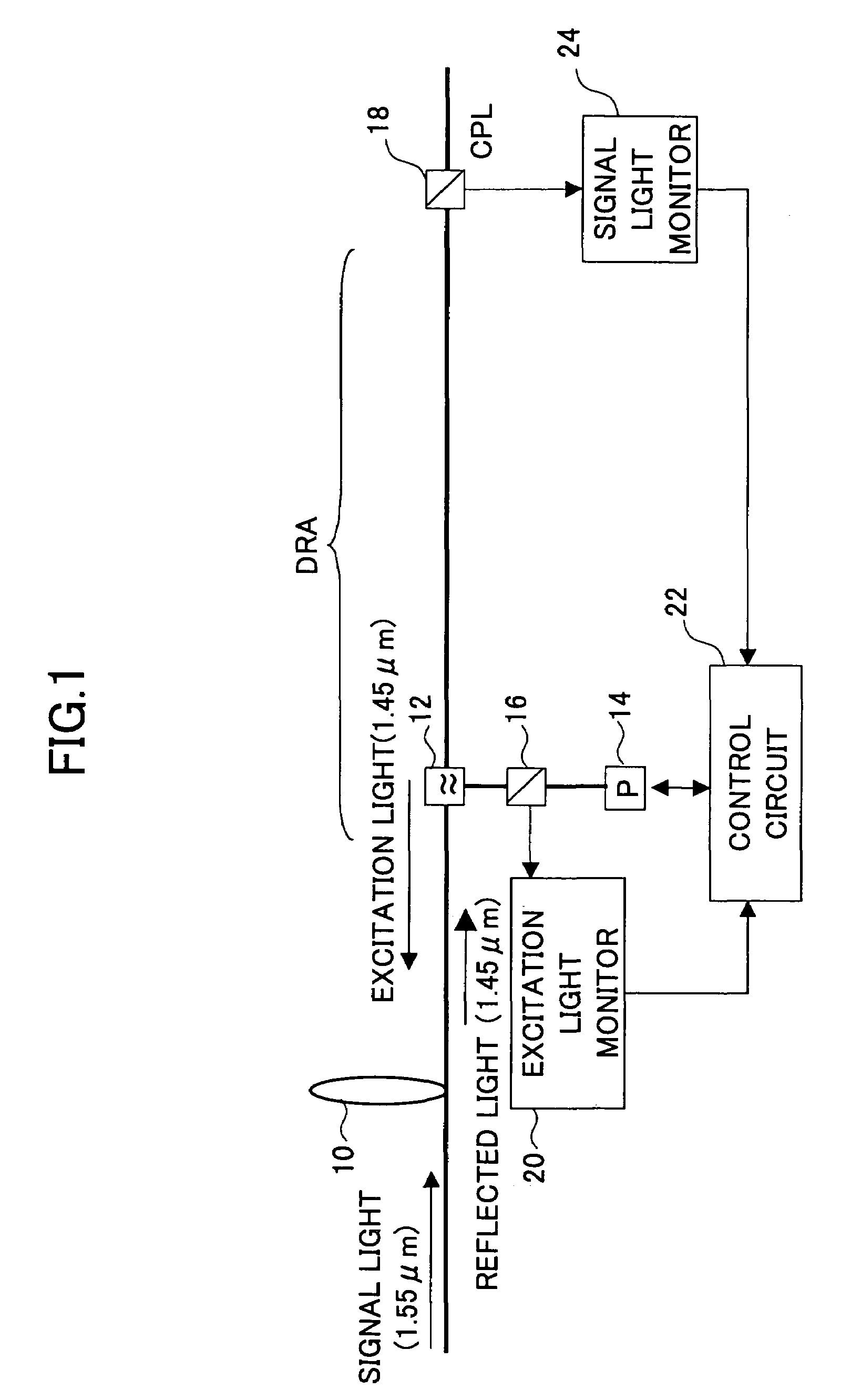
[0041]FIG. 5 shows a block diagram of a distributed Raman amplifier in the first embodiment of the present invention. As shown, a signal light for example with the wavelength of 1.55 μm is transmitted through an optical fiber 30 which is an optical transmission path. This signal light is applied to a band separation optical...

second embodiment

[0055]FIG. 11 shows a block diagram of a distributed Raman amplifier according to the present invention. In the figure, the same reference numeral is given to the same portion as that in FIG. 5. A point different from FIG. 5 is that a band separation optical coupler 39 is provided instead of the band separation optical coupler 38, in FIG. 11. In FIG. 11, through an optical fiber 30 which is an optical transmission path, a signal light for example with the wavelength of 1.55 μm is transmitted. This signal light is applied to the band separation optical coupler 32. An excitation light with the wavelength of 1.45 μm is supplied also to the band separation optical coupler 32 through an optical coupler 36 from an excitation light source 34, and, is applied, in a direction opposite to the transmission direction of the signal light, to the an optical fiber 30 with the band separation optical coupler 32.

[0056]Thereby, the signal light is amplified by using the optical fiber 30 as an amplify...

third embodiment

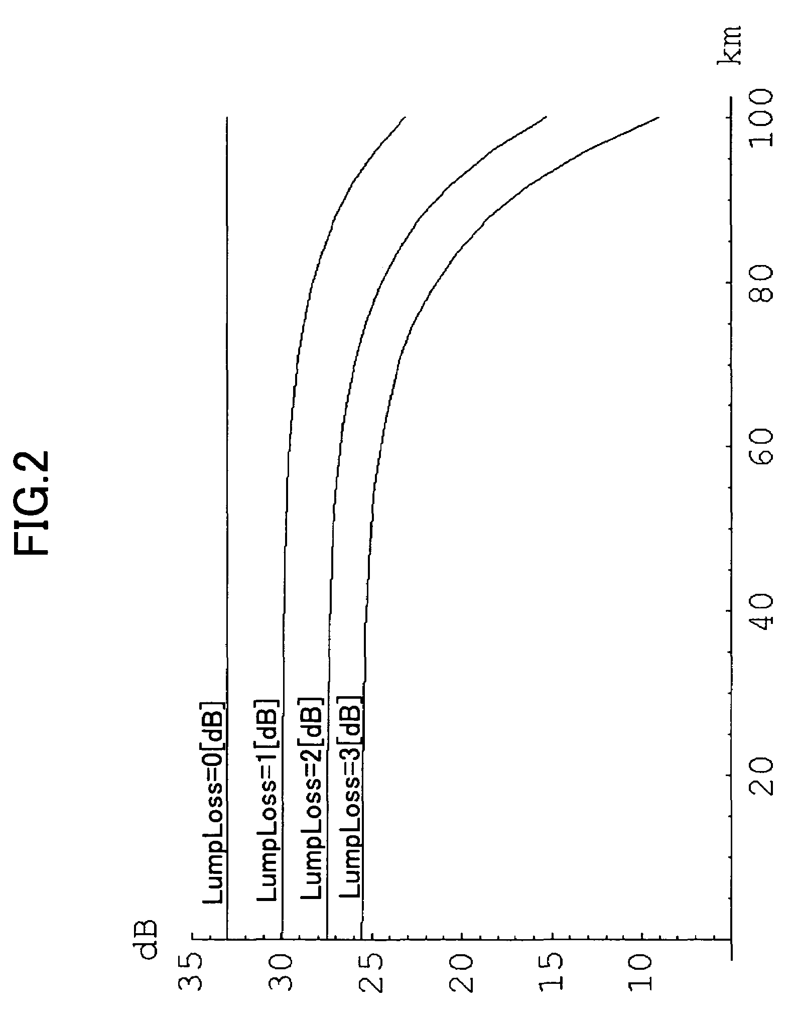
[0060]A control manner according to the present invention in which the excitation light power control is performed not monitoring the reflected light power but monitoring the scattered light power will now be described. When a loss point exists in an optical transmission path, the scattered light power ASS is small. On the other hand, the scattered light power ASS is large when there is no loss point. By utilizing this behavior, the control is made referring to a relation between the excitation light power P and the scattered light power ASS.

[0061]FIG. 12 shows a relation of the scattered light power ASS with respect to the excitation light power P in case of setting the length of the optical fiber transmission path as 100 [km] and the loss at a loss point as 1 [dB]. The five curves shown in the figure show the relations in case the loss point is located at a position of 0 [km], 90 [km], 95 [km], 99 [km], and 100 [km] from the point at which the excitation light is applied, respecti...


PUM

PropertyMeasurementUnit
wavelengthaaaaaaaaaa
lengthaaaaaaaaaa

Abstract

Power of scattered light separated from an optical transmission path is monitored, part of the excitation light is separated and power thereof is monitored, power of reflected light which passes in a direction opposite to a direction in which signal light passes through the optical transmission path is monitored, and, when monitored power of an excitation light reaches a predetermined determination value, whether or not any loss point occurs is determined, based on a ratio between the monitored power of the scattered light and the monitored power of the reflected light.

Description

BACKGROUND OF THE INVENTION[0001]1. Field of the Invention[0002]The present invention relates to a loss point detecting method and a distributed Raman amplifier applying the same, and, in particular, to a loss point detecting method used in an optical system and a distributed Raman amplifier applying the same.[0003]2. Description of the Related Art[0004]Recently, a demand for communications rapidly increases in many countries along with a sharp spreading of the Internet or a development of multimedia society. For the purpose of catching up therewith, introduction of a backbone optical transmission system applying a WDM (wavelength division multiplexer) technology has been proceeded with, whereby increase in the transmission capacity is directed to.[0005]In order to increase the transmission capacity, various methods such as time-division multiplexing, wavelength division multiplexing and so forth are considered, and, in particular, the method of wavelength division multiplexing is e...

Claims


Application Information

Patent Timeline
Patent Type & Authority Patents(United States)
IPC IPC(8): H01S3/00H04B10/08H04B10/12H04B17/00G02F1/35H01S3/067H01S3/10H01S3/131H01S3/30H04B10/03H04B10/071H04B10/077H04B10/079H04B10/29H04B10/293H04B10/294H04B10/564H04B10/572
CPCH01S3/302H01S3/06754H01S3/1301H01S2301/02H01S3/13013
Inventor KAMADA, TAKASHISEKIYA, MOTOYOSHIGOTO, RYOSUKE
Owner FUJITSU LTD
Why Eureka
Try Eureka