Stackable capacitor having opposed contacts for an implantable electronic medical device

a technology of electronic medical devices and capacitors, which is applied in the direction of electrolytic capacitors, liquid electrolytic capacitors, electrolytic capacitors, etc., can solve the problems of increasing the volume of the device, the design of current capacitors has some space inefficiencies, and the wiring connection is vulnerable to damag

Active Publication Date: 2006-04-18
PACESETTER INC
View PDF10 Cites 52 Cited by
  • Summary
  • Abstract
  • Description
  • Claims
  • Application Information

AI Technical Summary

Problems solved by technology

While generally effective, the current capacitor design has some space inefficiencies that increase device volume without increasing capacitance.
Moreover,

Method used


Image

  • Stackable capacitor having opposed contacts for an implantable electronic medical device
  • Stackable capacitor having opposed contacts for an implantable electronic medical device
  • Stackable capacitor having opposed contacts for an implantable electronic medical device

Examples


Embodiment Construction

[0014]The following description is of the best mode presently contemplated for practicing the invention. This description is not to be taken in a limiting sense but is made merely for the purpose of describing the general principles of the invention. The scope of the invention should be ascertained with reference to the issued claims. In the description of the invention that follows, like numerals or reference designators will be used to refer to like parts or elements throughout.

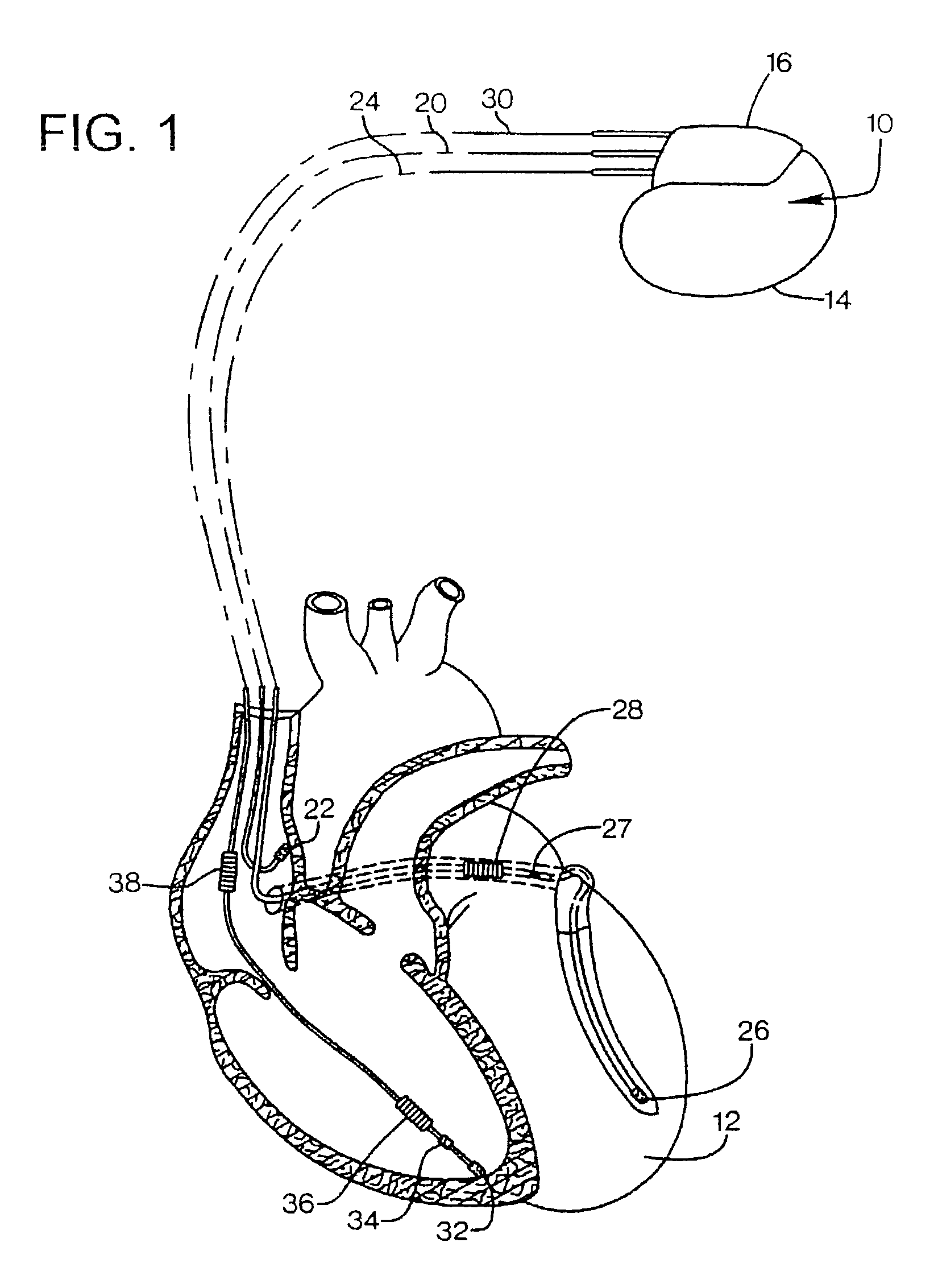
[0015]As shown in FIG. 1, there is a stimulation device 10 ore consistent with the preferred embodiment of the invention in electrical communication with a patient's heart 12 by way of three leads, 20, 24 and 30, suitable for delivering multi-chamber stimulation and shock therapy. To sense atrial cardiac signals and to provide right atrial chamber stimulation therapy, the stimulation device 10 is coupled to an implantable right atrial lead 20 having at least an atrial tip electrode 22, which typically is im...


PUM


Abstract

An implantable cardioverter-defibrillator has a housing containing cardioverter-defibrillator circuitry and a capacitor assembly. The capacitor assembly includes at least two flat capacitors each having opposed major surfaces. Each capacitor has an anode contact at one major surface, and a cathode contact at the opposite major surface. The anode contact of one of the capacitors contacts the cathode contact of the other. Each capacitor contact may be a thin metal plate covering the entire surface of the capacitor, with each plate connected to corresponding interleaved cathode or anode flat sheets between the plates. A non-conductive perimeter may enclose the sheets and connect the plates to each other.

Description

FIELD OF THE INVENTION[0001]This invention relates to electronic components for implantable medical devices, and more particularly to compact flat capacitors.BACKGROUND OF THE INVENTION[0002]Implantable Cardioverter Defibrillators (ICDs) are implanted in patients susceptible to cardiac tachyarrhythmias including atrial and ventricular tachycardias and atrial and ventricular fibrillation. Such devices typically provide cardioversion or defibrillation by delivering low voltage pacing pulses or high voltage shocks to the patient's heart, typically about 500–800V. The ICD operates by using sensors to detect a fast heart rate or tachyarrhythmia, upon which a battery within the device housing is coupled via an inverter to a high voltage capacitor or capacitor pair to charge the capacitors. When the capacitor reaches a desired voltage, charging is stopped and the capacitors are discharged under control of a microprocessor to provide a therapeutic shock to the patient's heart.[0003]The volu...

Claims


Application Information

Patent Timeline
IPC IPC(8): H01G9/04H01G2/10
CPCA61N1/3975H01G9/008A61N1/3981
Inventor FAYRAM, TIMOTHY A.
Owner PACESETTER INC
Why Eureka
Try Eureka