Electric double layer capacitor, electrolytic cell and process for fabricating same

a technology of double layer capacitors and electrolytic cells, which is applied in the direction of cell components, sustainable manufacturing/processing, electrical apparatus casings/cabinets/drawers, etc., can solve the problems of large vacant spaces at the corner portions of the mount area, difficult to efficiently arrange various electronic components, and difficult to seal off the interstices between metal cans with gaskets, etc., to achieve easy fabrication and increase length

Inactive Publication Date: 2006-04-18
SANYO ELECTRIC CO LTD
View PDF3 Cites 13 Cited by
  • Summary
  • Abstract
  • Description
  • Claims
  • Application Information

AI Technical Summary

Benefits of technology

[0022]The electric double layer capacitor and the electrolytic cell of the invention comprise the container half segments and lead members described above and can therefore be fabricated without bending the lead members after the container segments are made. With no great force applied to the lead members, the adhesion or intimate contact between the container and the lead members is unlikely to become impaired during the fabrication. The lead members are embedded in the container and bent as embedded in the resin forming the container (for example, in a wall portion or bottom portion), with the result that the lead members are in contact with the container at portions thereof having an increased length and a complex form. Especially the portion of the second lead member in contact with the container has an increased length since this lead member extends through the extension. With the capacitor and cell of the invention, therefore, it is difficult for the electrolyte in the container or the outside water to flow between the container and the lead members.
[0024]The process of the invention for fabricating an electric double layer capacitor or electrolytic cell is suitable for fabricating the capacitor or cell of the invention. With the process of the invention, the container half segments are made by insert molding using the lead members, which are bent before molding, as insert members. This eliminates the need to bend the lead members after the container segments are made. Electric double layer capacitors and electrolytic cells wherein the lead members are in contact with the container over complex areas of increased length can be fabricated easily by the process of the invention, while the outer end portions of the lead members are adjustable in length.

Problems solved by technology

However, if the coin-type electric double layer capacitor is provided in the rectangular mount area, the capacitor, which is in the form of a disk, leaves large vacant spaces at the corner portions of the mount area.
For this reason, it is difficult to efficiently arrange various electronic components including the capacitor on the circuit board to be used for mounting the capacitor.
However, when rectangular metal cans are used for conventional electric double layer capacitors, it is difficult to seal off the interstices between the metal cans with a gasket.
Furthermore, the water ingressing into the container 1 from outside by passing between the container 1 and the lead members 7, 8 becomes mixed with the electrolyte and is likely to impair the performance of the capacitor.
Additionally, the adhesion between the resin and the metal is generally low.
Aqueous or nonaqueous electrolytic cells resemble electric double layer capacitors in construction, so that the fabrication of aqueous or nonaqueous electrolytic cells having a resin container also involves the above problem.

Method used


Image

  • Electric double layer capacitor, electrolytic cell and process for fabricating same
  • Electric double layer capacitor, electrolytic cell and process for fabricating same
  • Electric double layer capacitor, electrolytic cell and process for fabricating same

Examples


first embodiment

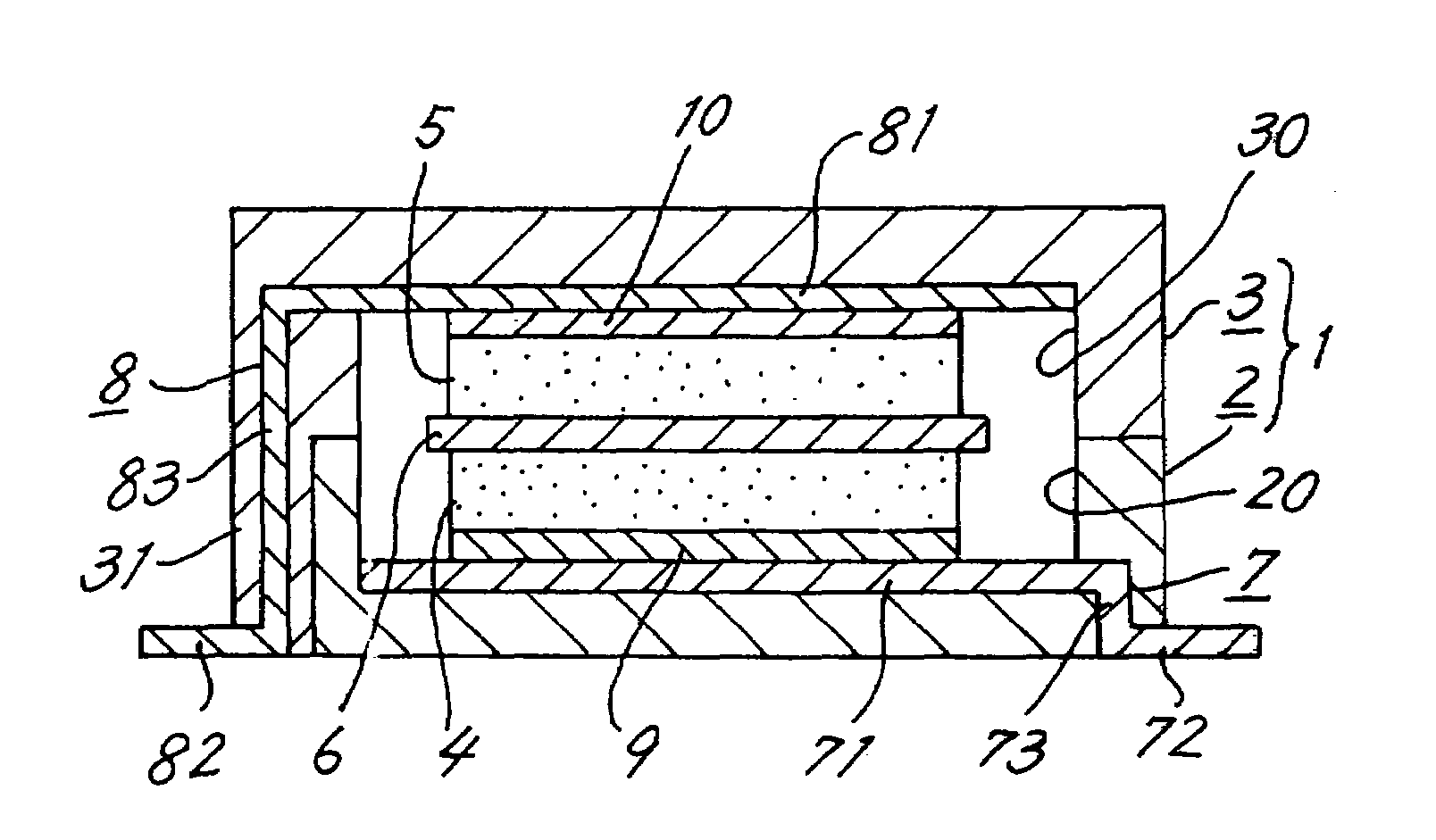
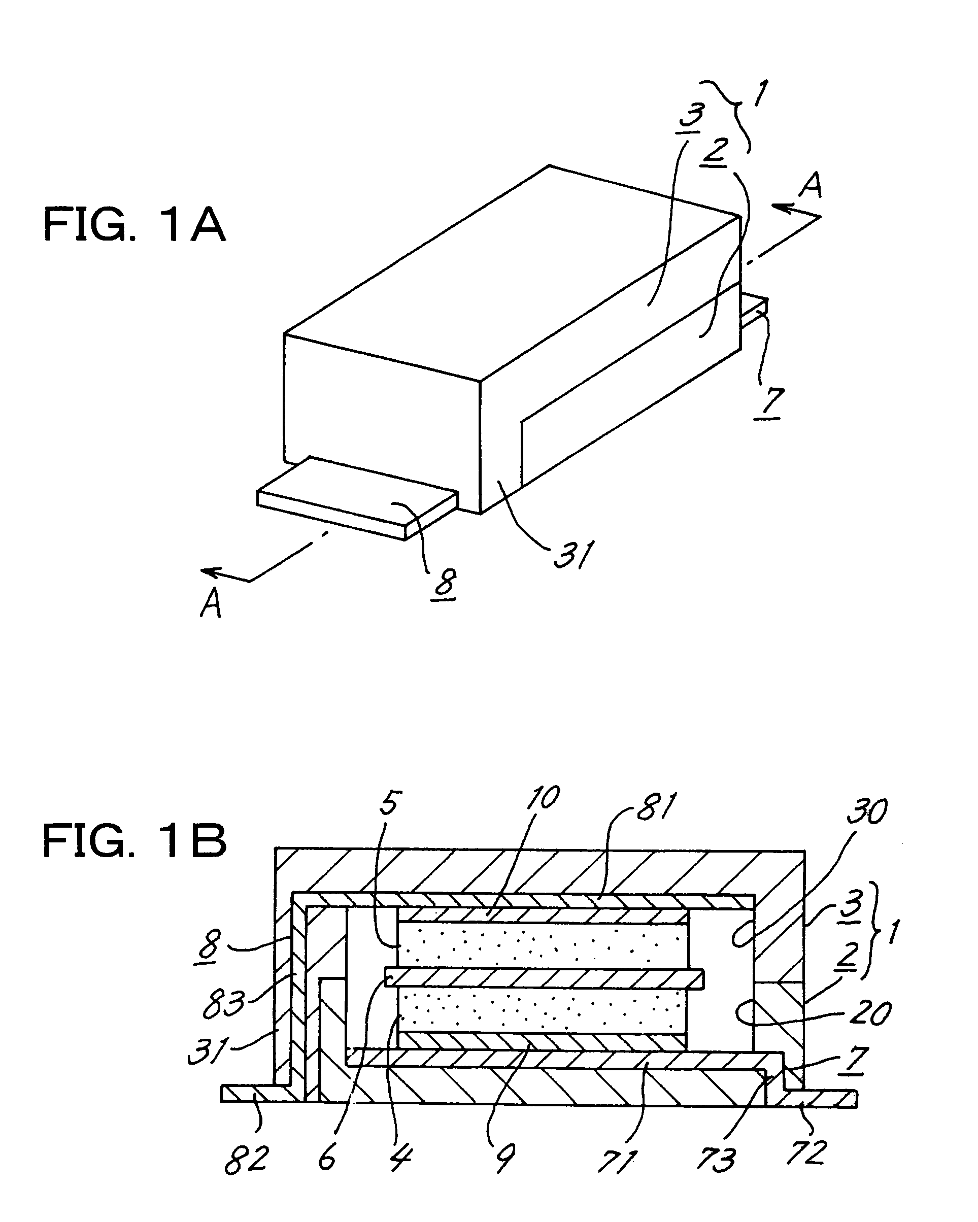
[0038]The present invention will be described below with reference to the drawings concerned. Throughout these drawings and FIGS. 13A to 13C, like parts are designated by like reference numerals. FIG. 1A is a perspective view showing the invention, i.e., an electric double layer capacitor, and FIG. 1B is a view in section taken along a vertical plane containing the line A—A in FIG. 1A and showing the capacitor as it is seen in the direction of the arrows shown.

[0039]With reference to FIG. 1A, the electric double layer capacitor of the present embodiment has a container 1 having a generally rectangular parallelepipedal contour and made of an insulating resin. The container 1 is made, for example, from epoxy resin, liquid crystal polymer (LCP), modified polyamide, nylon resin, polypropylene (PP) or like thermoplastic resin. The container 1 is made by joining a first container half segment 2 and a second container half segment 3 (see FIG. 4). The second container segment 3 is disposed ...

second embodiment

[0059]Next, a description will be given of an electric double layer capacitor of second embodiment of the invention. FIG. 5A is a perspective view of the capacitor, FIG. 5B is a view in section taken along a vertical plane containing the line B—B in FIG. 5A and showing the capacitor as it is seen in the direction of the arrows shown, and FIG. 5C is a view in section taken along a vertical plane containing the line C—C in FIG. 5A and showing the capacitor as it is seen in the direction of the arrows shown.

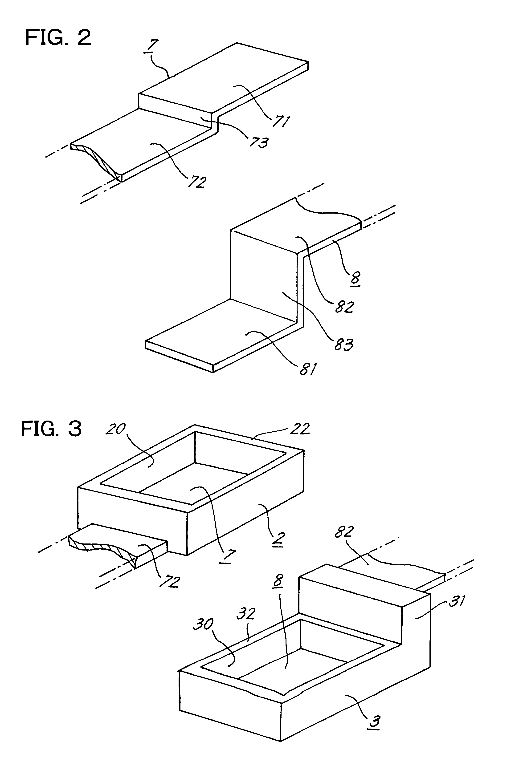
[0060]According to the first embodiment, the first and second lead members 7, 8 project outward from the respective two opposed side walls (extending the shorter side of the container 1) of the container 1 longitudinally of the container 1. According to the second embodiment, on the other hand, a first lead member 7 projects from one side wall (along the lengthwise direction of a container 1) of the container 1 in a direction along the short side of the container 1. The direction of...

third embodiment

[0064]FIG. 10 is a perspective view of the first and second container segments 2, 3 of the These segments 2, 3 are formed by insert molding in a process similar to those for the foregoing embodiments. The second flat plate portion 72 of the first lead member 7 projects from one side wall of the first container segment 2 (which wall is positioned along the short side of the segment 2) and is disposed closer to a (longitudinal) side wall of the first segment 2. The second flat plate portion 82 of the second lead member 8 projects from the outer side surface of an extension 31 of the second container segment 3 and is disposed closer to one (longitudinal) side wall of the second segment 3. A groove 33 is formed in the end of the extension 31 of the second segment 3 and is positioned closer to the other (longitudinal) side wall of the segment 3. When the first and second container segments 2, 3 are fitted together in combination, the second flat plate portion 72 of the first lead member...


PUM

PropertyMeasurementUnit
polarizableaaaaaaaaaa
areaaaaaaaaaaa
sizeaaaaaaaaaa

Abstract

The invention provides an electric double layer capacitor which has a container made from a resin in a substantially rectangular parallelepipedal form by joining a first container half segment and a second container half segment each in the form of a box. The second container segment is provided at one end thereof with an extension extending along an outer side surface of the first container segment to the bottom outer surface thereof. A first lead member has a portion closer to one end thereof, embedded in the first container segment, the first lead member portion, bent as embedded in the first container segment and led out of the container to outside thereof. A second lead member has a portion closer to one end thereof, embedded in the second container segment, bent as embedded in the second container segment and extending through the extension to outside of the container. The first lead member portion and the second lead member portion have respective outer ends projecting outward from the container and arranged on substantially the same plane as the outer lower surface of the container.

Description

TECHNICAL FIELD[0001]The present invention relates to electric double layer capacitors and electrolytic cells having a container of resin and a process for fabricating these devices.BACKGROUND ART[0002]Small-sized electric double layer capacitors of the coin type are in wide use for cellular phones, digital cameras and like electronic devices mainly as backup power sources. As is well known, the electric double layer capacitor of the coin type comprises a pair of polarizable electrodes having a separator interposed therebetween and housed in an inside space defined by a pair of metal cans arranged as insulated from and opposed to each other. The polarizable electrodes and the separator are impregnated with an aqueous or nonaqueous electrolyte.[0003]For use on circuit boards, electronic components have been made in chip form in increasing quantities, so that rectangular areas are generally provided on circuit boards for mounting electric double layer capacitors thereon. However, if t...

Claims


Application Information

Patent Timeline
Patent Type & Authority Patents(United States)
IPC IPC(8): H01G2/10H01G11/00H01G9/00H01G9/06H01G9/08H01G11/40H01G11/42H01G11/74H01G11/78H01G11/82H01G11/84H01M2/02H01M2/06H01M2/30H01M6/00H01M10/04
CPCH01G9/016H01G9/058H01G9/06H01G9/08H01G11/74H01G11/78H01G11/84H01G9/155Y10T29/417Y02E60/13H01G11/22Y02P70/50H01G11/80
Inventor OMURA, SEIJIITO, KIYOTAKA
Owner SANYO ELECTRIC CO LTD
Why Eureka
Try Eureka