Apparatus and method for identifying cable phase in a three-phase power distribution network

a technology of power distribution network and cable phase, which is applied in the direction of noise figure or signal-to-noise ratio measurement, phase sequence/synchronization indication, instruments, etc., can solve the problems of line being erroneously removed from a more lightly loaded phase, affecting the service of all customers on the branch being re-phased, and changing the load of each single-phase outpu

Inactive Publication Date: 2006-04-18
PIESINGER GREGORY H
View PDF14 Cites 56 Cited by
  • Summary
  • Abstract
  • Description
  • Claims
  • Application Information

AI Technical Summary

Benefits of technology

[0017]In this way, the worker determines the line phase by taking a simple meter measurement in much the same way voltag

Problems solved by technology

However, over time, as customers are added and removed, the loads on each single-phase output may change and become unbalanced.
Otherwise, a line may be erroneously removed from a more lightly loaded phase and placed on a more heavily loaded phase.
If this happens, the procedure will have to be repeated, which will cause a second disruption in service to all customers on the branch being re-phased.
In the worst case, adding a greater load to the more heavily loaded phase may cause a substation fuse to blow, resulting in a power outage for all customers on the overloaded phase.
This can

Method used


Image

  • Apparatus and method for identifying cable phase in a three-phase power distribution network
  • Apparatus and method for identifying cable phase in a three-phase power distribution network
  • Apparatus and method for identifying cable phase in a three-phase power distribution network

Examples


Embodiment Construction

[0028]This discussion is concerned with power distribution at both 60 and 50 Hertz (Hz). To avoid confusion, all references to parameters of 50-Hz systems will be bracketed and will follow the same parameters for 60-Hz systems. For example, the phrase “for power at 60 [50] Hz, each cycle takes 16.67 [20.0] milliseconds” indicates that in a 60-Hz system each cycle takes 16.67 milliseconds, while in a 50-Hz system each cycle takes 20.0 milliseconds.

[0029]Also, it will be noted that in the preferred embodiments discussed herein mention is made of 120-volt and 240-volt commercial and residential voltages. Those skilled in the art will appreciate that these voltages are standard in the U.S. The use of other voltages, such as the 230-volt E.U. standard, does not depart from the spirit of the present invention.

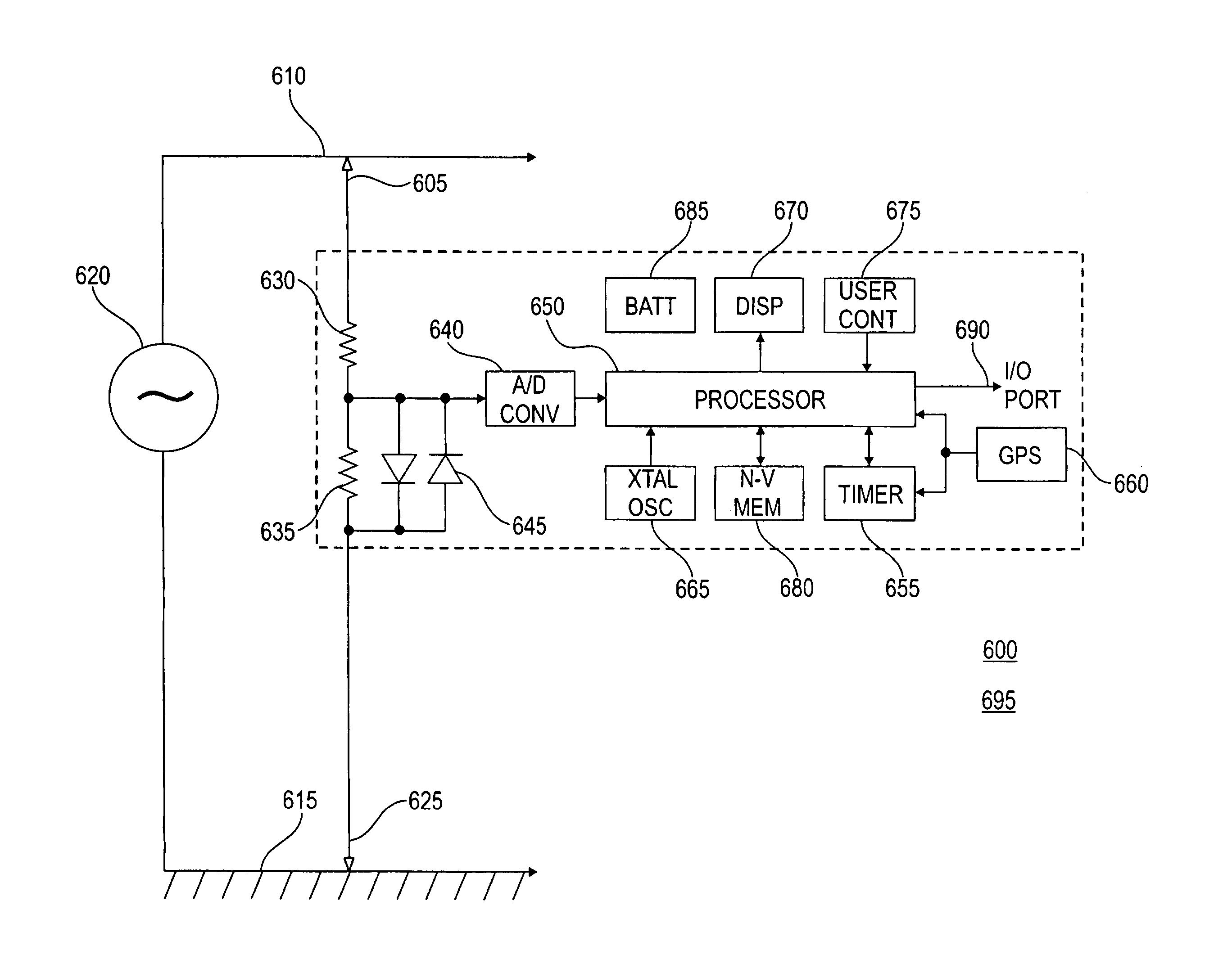
[0030]The goal of the present invention is to provide the utility worker with an easy to use phase identification apparatus and method for identifying the phase of a line in a three-...


PUM


Abstract

A line phase identification system and method identifies the phase of a power line at a remote unknown-phase line (160) in a three-phase power distribution network (100). The instantaneous phase of a known-phase line (150) is measured and saved each GPS second using a 1-pps time mark of a GPS receiver (660). The instantaneous phase at the unknown-phase line (160) is measured at a single GPS second using the 1-pps time mark of a GPS receiver (660) and compared to the phase measurement taken from the known-phase line (150) at the same GPS second. The differential phase between these simultaneously taken known and unknown instantaneous phases will be close to either 0, +120, or −120 degrees, thus identifying the line phase at the line under test (160).

Description

RELATED APPLICATIONS[0001]The present patent is a United States National Conversion of “Apparatus and Method for Identifying Cable Phase in a Three-Phase Power Distribution Network,” PCT Application No. PCT / US2003 / 007199, which is a continuation-in-part of “Apparatus and Method for Identifying Cable Phase in a Three-Phase Power Distribution Network,”, U.S. patent application Ser. No. 10 / 317,910, filed on 12 Dec. 2002, now U.S. Pat. No. 6,667,610 B2, which is incorporated herein by reference.[0002]The present invention claims benefit under 35 U.S.C. §119(e) to “Apparatus and Method for Determining Identifying Cable Phase in a 3-Phase Power Distribution Network,” U.S. Provisional Patent Application Ser. No. 60 / 363,076 filed 11 Mar. 2002, which is incorporated by reference herein.TECHNICAL FIELD[0003]The present invention relates to the field of three-phase power distribution networks. More specifically, the present invention relates to the field of identifying the phase of a power lin...

Claims


Application Information

Patent Timeline
IPC IPC(8): G01R25/00G01R29/18
CPCG01R29/18
Inventor PIESINGER, GREGORY H.
Owner PIESINGER GREGORY H
Why Eureka
Try Eureka