
System for characterizing simulated circuit logic and behavior

a logic and logic model technology, applied in the field of systems for modeling the logic and behavior of electronic circuits, can solve the problems of difficult analysis, difficult for a design engineer to relate the behavior and logic models, and difficult to figure out how even simple circuits work, etc., to achieve the effect of easy understanding for a design engineer

Inactive Publication Date: 2006-04-18
SYNOPSYS INC
View PDF8 Cites 11 Cited by
  • Summary
  • Abstract
  • Description
  • Claims
  • Application Information

AI Technical Summary

Benefits of technology

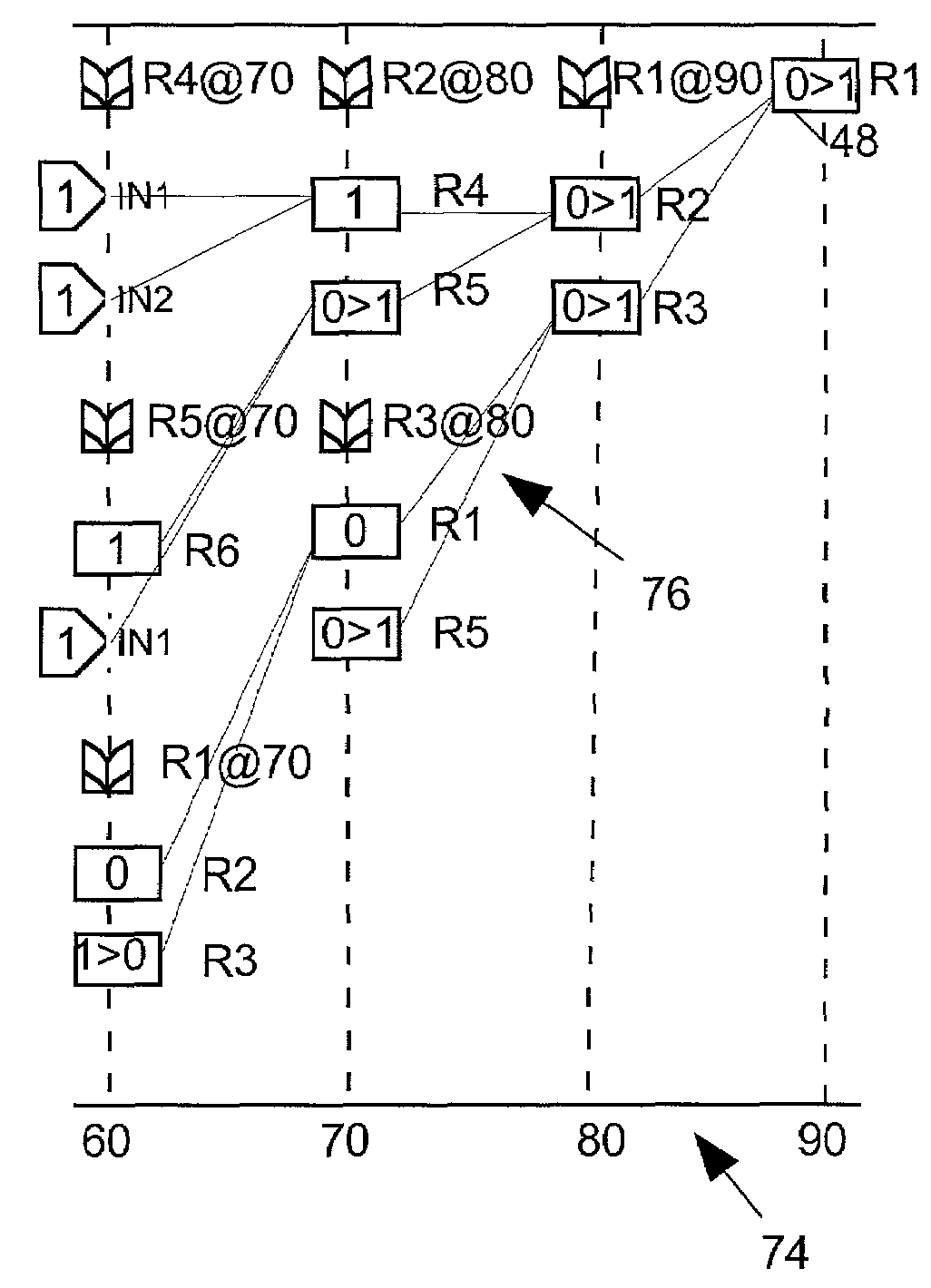
[0018]It is accordingly an object of the invention to provide a system for concurrently modeling both the logic and the behavior of a circuit in a way that makes it easier for a design engineer to understand the logical causes and effects of various signal events.

Problems solved by technology

However since it is usually hard to figure out how even simple circuits would respond over a long period of time to various input signal patterns, designers normally use computer-based circuit simulators to do the job for them.
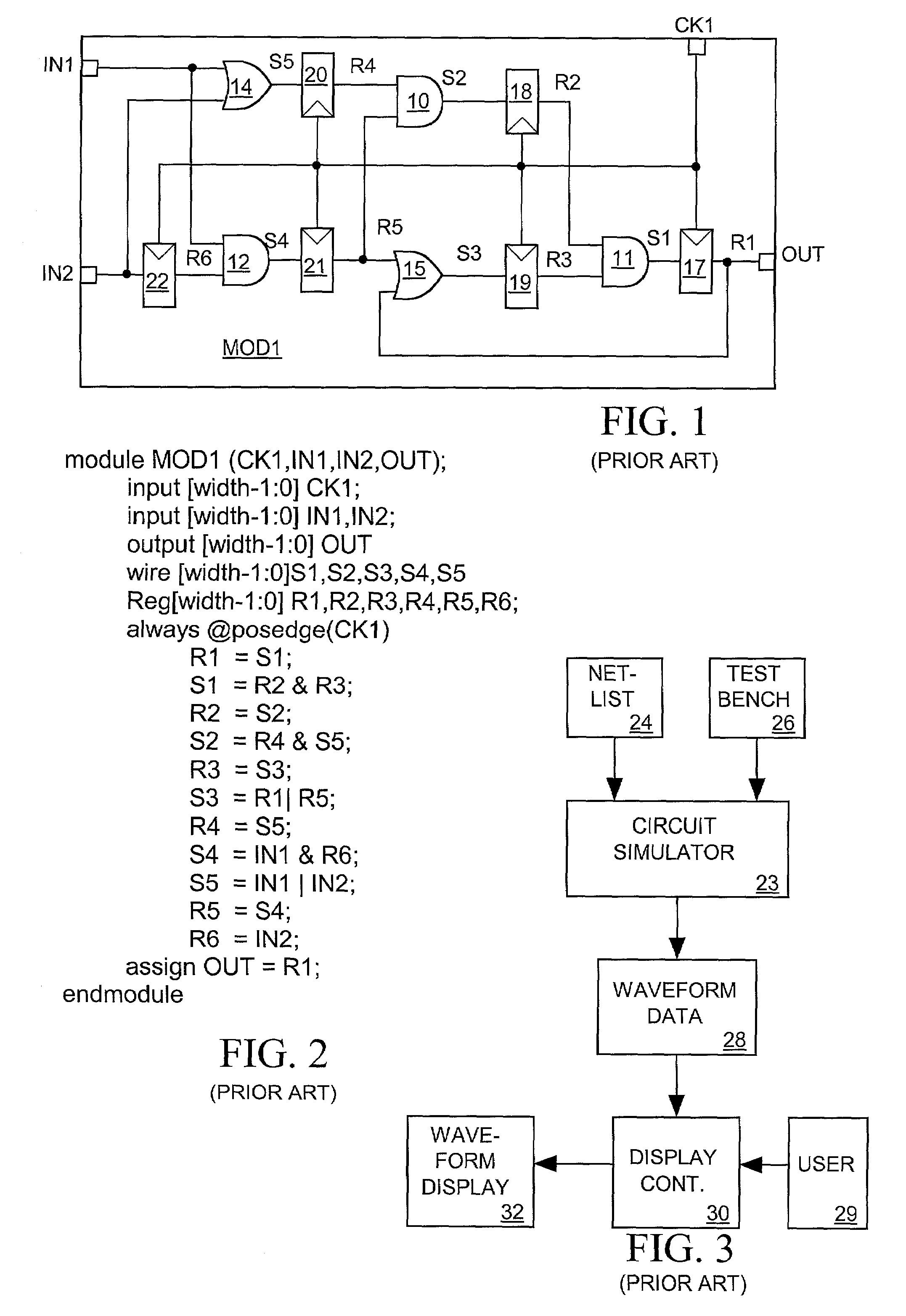
Although a human or a circuit simulator can deduce how module MOD1 might respond over time to various input signal patterns based on information presented by those models, the schematic and netlist models themselves do not directly represent the temporal behavior of the signals the module generates in response to its input signals.
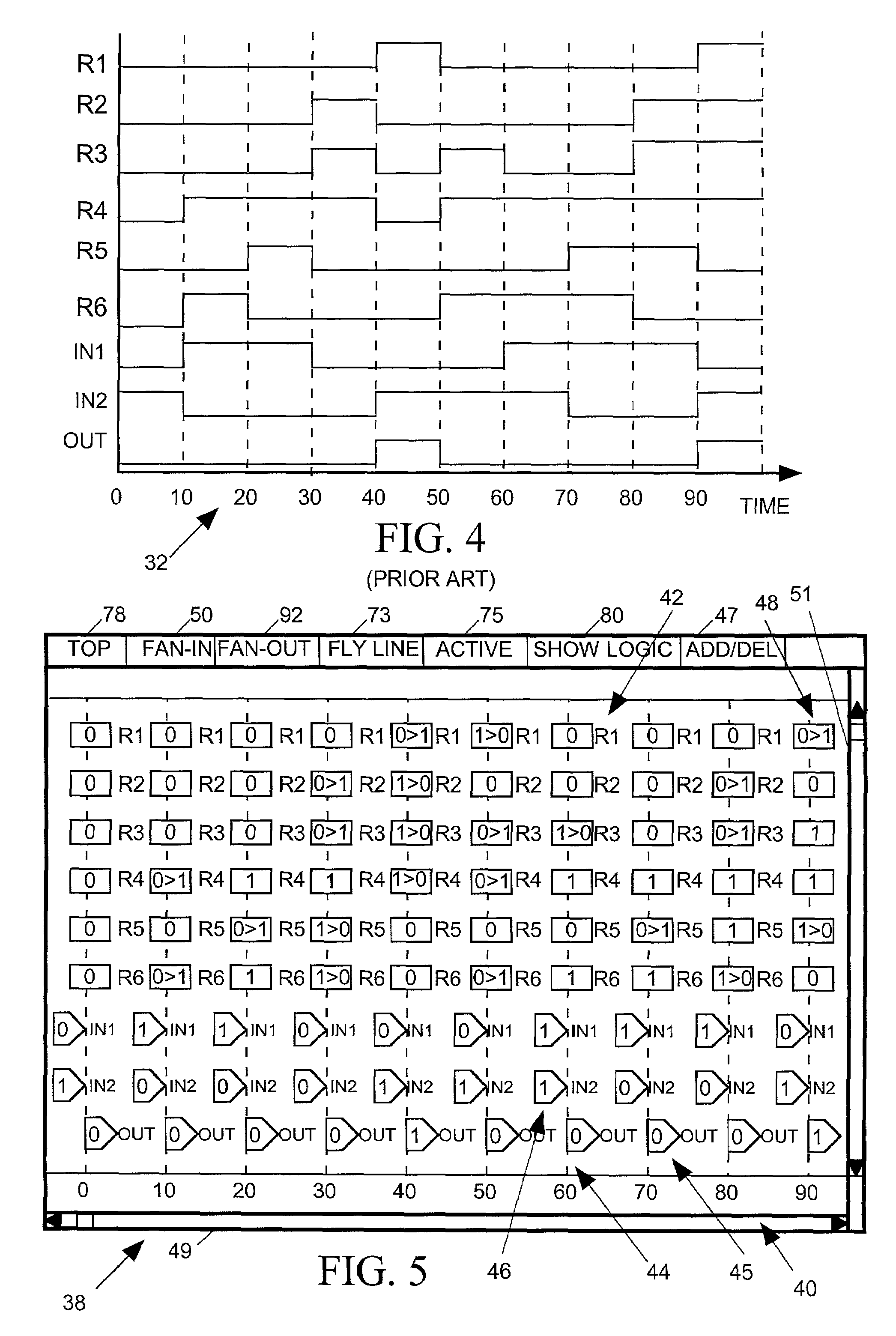
However these are not logic models because they do not tell us anything about the structure of the circuit that makes those signals behave that way.
That type of analysis helps design engineers to pinpoint logic errors in a circuit design, but they often find such analysis difficult because it requires them to correlate two different circuit models, the behavioral model of FIG. 4 and the logic model of FIG. 1 or 2.
However it can be hard for a design engineer to relate the behavior and logic models when the circuit being modeled is large and complex.
When a design engineer is trying to figure out why a particular signal behaves as it does in a behavior model, the logic model he or she studies for an answer can in some sense present too much information.
The problem of relating circuit behavior to circuit logic compounds as the design engineer looks farther backward in time from a circuit event of interest to determine the logical cause of the event.
However as the design engineer goes farther back time looking for signal events having an influence on the signal event occurring at time 90 the number of signal events that must be considered grows and the logic involved can become quite complicated, particularly when the circuit includes feedback loops.
Similarly when the design engineer wants to determine, for example, how a state change in the R6 signal at time 10 might have affected states of various signals thereafter, the logical relationship between that R6 signal state change and a state change in other signals many clock cycles later can be very complex and difficult to determine from the circuit schematic, particularly where the circuit includes feedback.

Method used


Image

  • System for characterizing simulated circuit logic and behavior
  • System for characterizing simulated circuit logic and behavior
  • System for characterizing simulated circuit logic and behavior

Examples


Embodiment Construction

[0032]Prior art systems for modeling a circuit typically characterize a circuit either in terms of its logic or in terms of the behavior of the signals it produces. Thus in order to determine how a circuit's logic affects the behavior of its signals circuit design engineers have had to correlate two different types of circuit models. The present invention relates to a system for generating and displaying a “temporal schema” model of a circuit in various levels of detail. The temporal schema model incorporates both the logic and behavioral aspects of the circuit, and displays based on the temporal schema model make it easier for viewers to correlate circuit logic and behavior.

[0033]FIG. 1 illustrates a typical prior art schematic diagram modeling the logic of one small module MOD1 of an integrated circuit. The schematic diagram labels the various input (IN1 and IN2), output (OUT), register output signals (R1–R6) and other internal signals (S1–S5) and shows how they are logically rela...


PUM


Abstract

A circuit simulator simulates a circuit described by a circuit logic model as having a set of clocked registers interconnected by un-clocked logic to produce waveform data indicating states of each circuit input signal and of each register output signal as functions of clock signal edge timing. The waveform data and the logic model are then processed to produce a temporal schema model characterizing the circuit's logic and behavior. A display based on the temporal schema model depicts circuit behavior using separate symbols to represent successive circuit input signal states and register output signal states at various times during the simulation. The same display also graphically depicts fan-in or fan-out logical relationships by which circuit input signal states and register output signal states influence register input signal states.

Description

BACKGROUND OF THE INVENTION[0001]1. Field of the Invention[0002]The present invention relates in general to systems for modeling the logic and behavior of electronic circuits, and in particular to a system for characterizing an electronic circuit in a manner that graphically correlates its logic to its behavior.[0003]2. Description of Related Art[0004]A circuit designer can model an integrated circuit in several ways. For example FIG. 1 illustrates a schematic diagram modeling one small module MOD1 of an intigrated circuit. The schematic diagram models the logic of module MOD1 indicating that it includes AND gates 10–12, OR gates 14–15 and six registers 17–22 and showing how the parts are interconnected. The schematic diagram also labels the various input, output and internal signals and shows how they are logically related by using symbols to represent OR, AND and register logic operations. While the schematic diagram does not directly indicate how any of the signals the circuit ge...

Claims


Application Information

Patent Timeline
IPC IPC(8): G06F3/147G06F3/153G06F17/50
CPCG06F17/5022G06F30/33
Inventor HSU, YU-CHINTSAI, FURSHINGLIU, TAYUNGTABBARA, BASSAMHO, KUNMINGBAKEWELL, GEORGECHEN, YIRNG-ANSANDLER, SCOTT
Owner SYNOPSYS INC
Learn More