Lighting system for enclosures

a technology of enclosures and light sources, applied in the direction of lighting and heating apparatus, semiconductor devices for light sources, lighting support devices, etc., can solve the problems of incandescent lamps still generating significant heat, high current devices giving a harsh light dramatically different, and requiring heavy connective wiring, etc., to achieve intense light, long service life, and small size

Inactive Publication Date: 2006-04-25
SPAHR MARTIN R
View PDF9 Cites 37 Cited by
  • Summary
  • Abstract
  • Description
  • Claims
  • Application Information

AI Technical Summary

Benefits of technology

[0025]These and other objects are accomplished by the invention herein disclosed which is a portable lighting system for enclosures utilizing advanced battery and LED technology to achieve a device having small size, intense light, a long service life and low cost. The disclosed system includes a light and a magnet. The light may be automatically activated by cooperative action between the magnet mounted to the enclosure door and the light, or manually activated by a switch. The light is sealed to prevent corrosion of the internal components. In some embodiments the battery is replaceable; in others the case of the light is sealed at manufacture and the device discarded when the battery life is exhausted. In one embodiment the device size is minimized, the size being determined principally by the size of the battery and other components enclosed in the case of the device; in another embodiment the size is somewhat larger so as to permit the removable attachment of various lenses and reflectors which direct and control dispersion of light from the device. A mounting means is attached to the interior of the enclosure by adhesive or fasteners. The light is removably mounted to the mounting means by hook and loop fasteners or similar so that when an enclosure is opened the light may be removed from the mount and used as a hand-held light or removably mounted, for instance, to the bill or brim of a hat, to a belt or other clothing, or to another object by a means provided.

Problems solved by technology

These low resistance, high current devices gave a harsh light dramatically different from the gas or oil lamps then in general use, and required heavy connective wiring due to their high current use.
Also, because of the high current requirements and associated high power losses in the connective wiring, the power source was located in close proximity to the arc-lamp(s).
While Edison's incandescent lamp had real advantages over arc lamps, the incandescent lamp still generated significant heat.
Although the heat generated could, in some cases, cause problems, the greater significance of the heat was that it represented power consumption which did not result in light generation.
Incandescent lamps have relatively low efficiency.
The requirement for small size in a battery-powered lighting device conflicts with the requirement for sufficient light generation for a useful length of time.
Increasing the power and energy requirements (illumination output and time) increases the size of the battery required, which increases the size of the device.
A lamp which is inefficient, that is, one in which a large portion of the power supplied produces heat rather than light, will require a relatively larger battery than a more efficient lamp for a given application.
Their best efficiency, however, is inferior to that of Light Emitting Diodes (LEDs), more recently developed electronic devices which emit light.
Early LEDs had high efficiency but low light output.
The lighting of small, portable or fixed enclosures is frequently problematic in that the lighting system often must have its own power source, and must be of a size which will not occupy an unacceptably large portion of the enclosure or interfere with the function of the enclosure.
Additionally, an enclosure may not be opened for an extended period of time during which the lighting system may be exposed to humid air, or even corrosive atmospheres as in the case of enclosures on boats or those exposed to weather.
The device as described is unacceptably large for lighting small enclosures and is not sealed, making it unsuited for the lighting of enclosures exposed to weather or humidity due to likely corrosion.
The unit is not sealed making it suitable only for enclosures having a controlled environment to prevent corrosion of the mechanism, circuitry and batteries.
The light described would be useful for lighting other enclosures having doors with a horizontal hinge, however, the light as described has multiple sites through which liquid and or water vapor can enter the device and corrode internal components.
The life of the device is likely to be limited by corroding of internal components due to exposure to humidity of the surrounding air.
Plunger devices are difficult to seal making them susceptible to corrosion of their components.
The device does not, however, have a method for overriding activation.
This would be unacceptable for many other enclosures.
They may be applicable to many tool boxes, fishing tackle boxes and mail boxes, however, when used on a portable enclosure like tool and tackle boxes the light may be activated if the box itself is tipped, thereby draining the battery.
Such devices are frequently difficult to seal for the purpose of corrosion prevention, and are prone to sticking if they are left for long periods of time without movement as would be the case, for instance, in a home electrical box.
The prior art devices previously herein discussed are poorly suited to the illumination of small enclosures such as tool boxes, boxes for fishing tackle, mail boxes, electrical boxes or cabinets in commercial vehicles which may be exposed to humid air or weather.
None of the prior art devices previously herein discussed has the desired combination of features.

Method used


Image

  • Lighting system for enclosures
  • Lighting system for enclosures
  • Lighting system for enclosures

Examples


Embodiment Construction

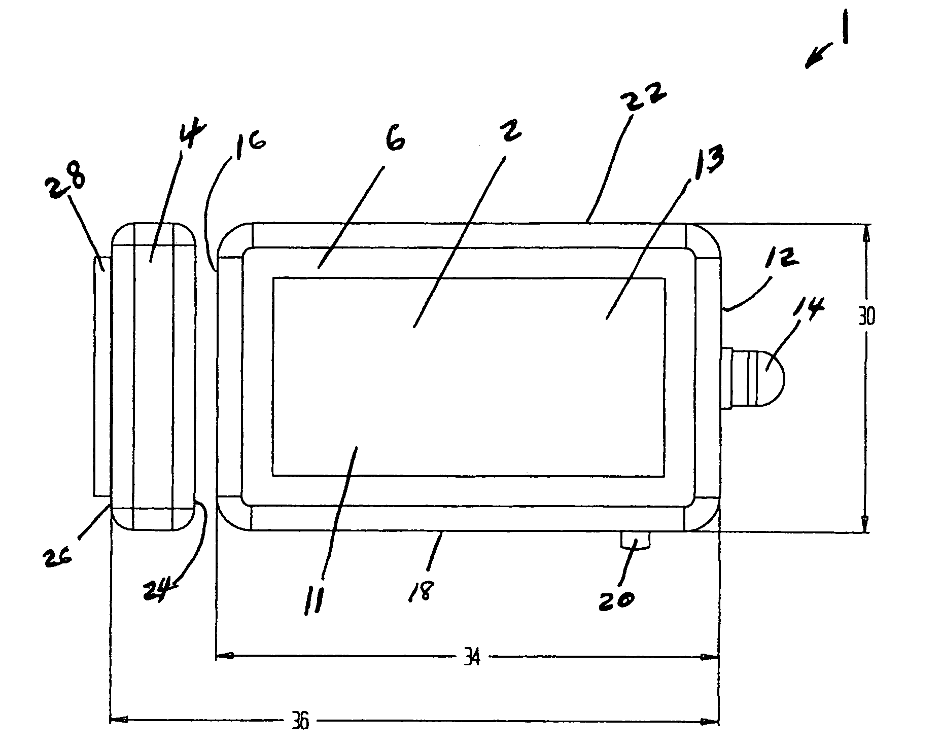
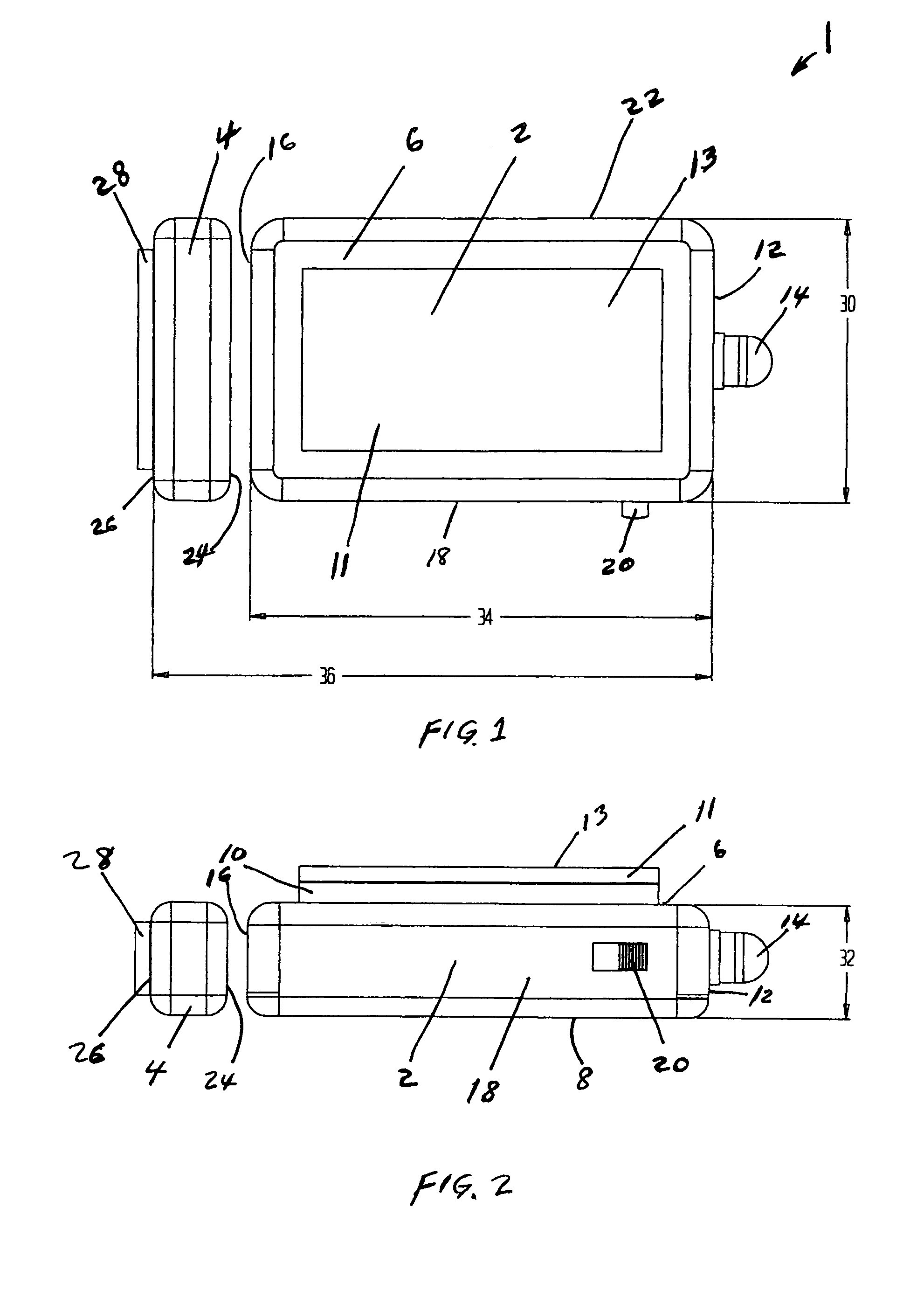
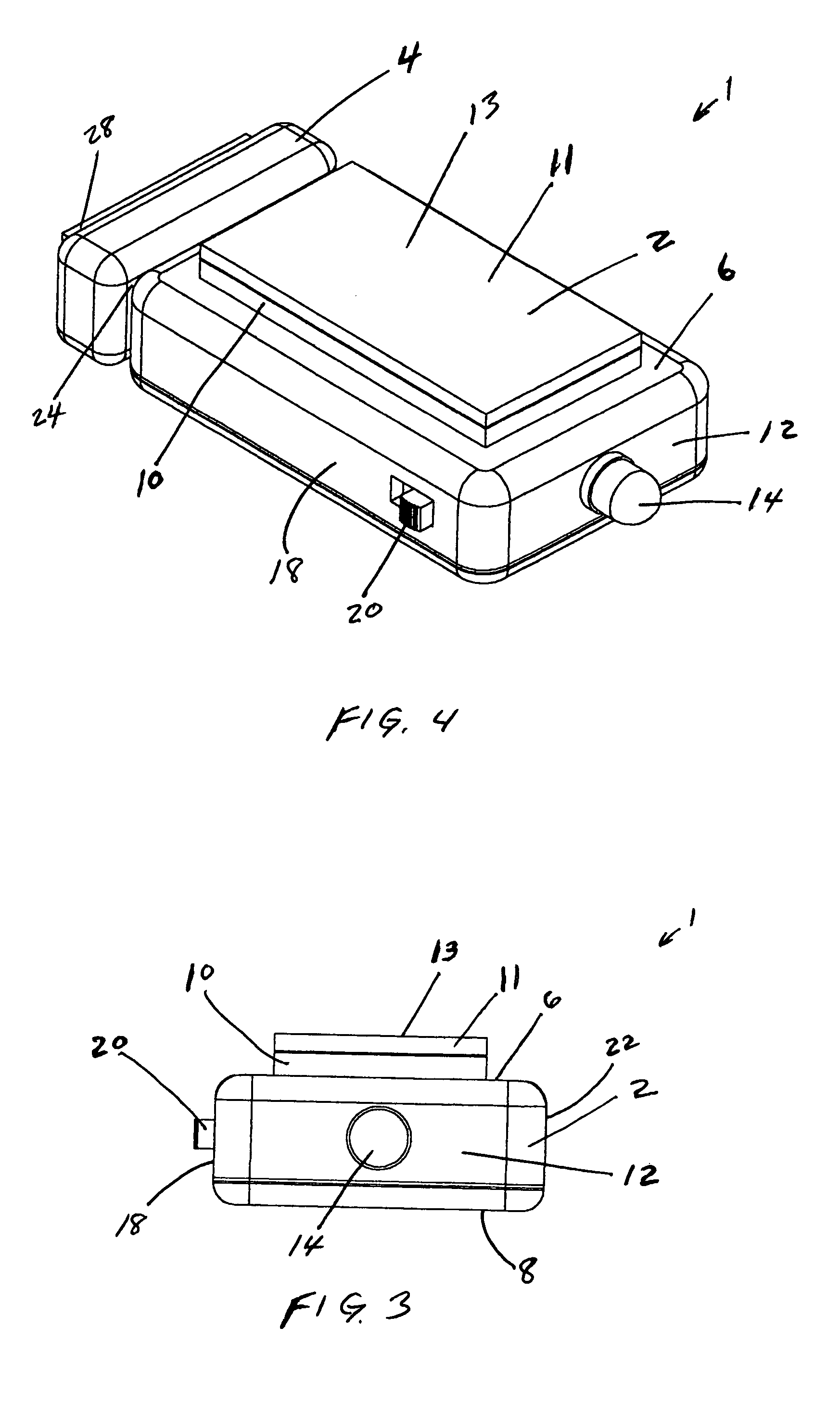
[0047]Referring to the Figures, as seen in FIGS. 1 through 4 showing a lighting system formed in accordance with the principles of this invention, enclosure light 1 has a body 2 and an associated magnetic piece 4. Magnetic piece 4 is composed of a magnet surrounded by a suitable polymeric material. Body 2 has a top surface 6 and a bottom surface 8, surface 6 having attached thereto hook fastener material 10. Body 2 also has a first end surface 12 from which protrudes LED 14, a second end surface 16, a first lateral surface 18 from which protrudes the slide portion of switch 20, and a second lateral surface 22. Magnetic piece 4 has first end surface 24 and a second end surface 26, surface 26 having affixed thereto adhesive strip 28. Loop material 11 is removably affixed to hook material 10, top surface 13 of material 11 is coated with an adhesive material. The disclosed device is compact, width 30 being about 1.1 inches, height 32 being about 0.45 inches, body length 34 being about 1...


PUM


Abstract

A portable lighting system for small enclosures is provided. A light is removably attached to the interior of an enclosure. Activation may be automatic by cooperative interaction between the light and a magnet affixed to a movable portion of the enclosure or by a manual switch. The light may be detached from the interior and used as a hand-held light or attached to an article of clothing or an object. A manual switch allows the light to be deactivated when illumination is not required.

Description

PRIORITY[0001]This application claims the benefit of provisional application 60 / 499,307 filed Sep. 2, 2003.BACKGROUND OF THE INVENTION[0002]The present invention relates to portable light systems and more particularly to a compact, portable, self-contained light system for enclosures.[0003]The electrical lighting of enclosed spaces such as auditoriums began with arc lamps powered by either storage batteries or by dynomotors. These low resistance, high current devices gave a harsh light dramatically different from the gas or oil lamps then in general use, and required heavy connective wiring due to their high current use. Also, because of the high current requirements and associated high power losses in the connective wiring, the power source was located in close proximity to the arc-lamp(s). Thomas Edison created a high resistance, incandescent lamp that gave a “soft” light similar to that of a gas lamp. Because the lamp resistance was high, the current requirement was low thereby a...

Claims


Application Information

Patent Timeline
Patent Type & Authority Patents(United States)
IPC IPC(8): F21V33/00A47G29/30B60Q3/02F21L4/02F21V14/04F21V21/08F21V23/04F21V31/00
CPCA47G29/30B60Q3/022B60Q3/0269F21V21/08F21V21/0832F21V23/04F21V31/00F21L4/027F21V7/0075F21V14/04Y10S362/802F21Y2101/02Y10S362/80F21V14/045F21Y2115/10B60Q3/225B60Q3/59
Inventor SPAHR, MARTIN R.VAN WYK, ROBERT ALLEN
Owner SPAHR MARTIN R
Why Eureka
Try Eureka