Tool for surface treatment of an optical surface

a technology for optical surfaces and tools, applied in the field of surfacing optical surfaces, can solve the problems of reducing the diameter of the tool, and reducing the “lift” or “seating” of the tool, so as to achieve stable surfacing, reliable and fast surfacing, and good quality

Inactive Publication Date: 2006-04-25
ESSILOR INT CIE GEN DOPTIQUE
View PDF10 Cites 8 Cited by
  • Summary
  • Abstract
  • Description
  • Claims
  • Application Information

AI Technical Summary

Benefits of technology

[0020]Thus the invention aims in particular to solve the problems previously cited by proposing a surfacing tool which, whilst being suitable for a sufficiently vast range of optical surfaces, in terms of curvature (convexity, concavity) and shape (spherical, toric, aspherical, progressive or any combination thereof, or more generally “freeform”), is stable during surfacing and allows reliable and fast surfacing of good quality at reduced cost.

Problems solved by technology

This type of tool is particularly unsuitable for surfacing optical surfaces of complex shape, known as “freeform” surfaces, in particular aspherical surfaces, which by definition have a non-uniform curvature.
Furthermore, this type of tool is also unsuitable for optical surfaces having too marked a difference of convexity or concavity relative to the tool: in the former case, the edges of the tool lose contact with the optical surface; in the latter case it is the central portion of the tool that loses contact with the optical surface, as a result of which surfacing is incomplete.
However, restricting the diameter of the tool reduces its “lift” or “seating” and therefore its stability on the optical surface during surfacing.
Now this kind of control requires the use of complex means such as a numerically controlled machine, the cost of which is generally high and may even prove prohibitive for a surfacing operation.
However, because of shear forces, the interface then tends to warp or to be offset laterally, to the detriment of the efficiency and accuracy of the tool.
Furthermore, shear causes fast wear, or even destruction, of the interface.
Finally, the flexibility of the interface encourages and accentuates the effects of the buffer scraping against the edge of the lens, which may eventually lead to the risk of premature and / or inopportune destruction of the tool.

Method used


Image

  • Tool for surface treatment of an optical surface
  • Tool for surface treatment of an optical surface
  • Tool for surface treatment of an optical surface

Examples


Embodiment Construction

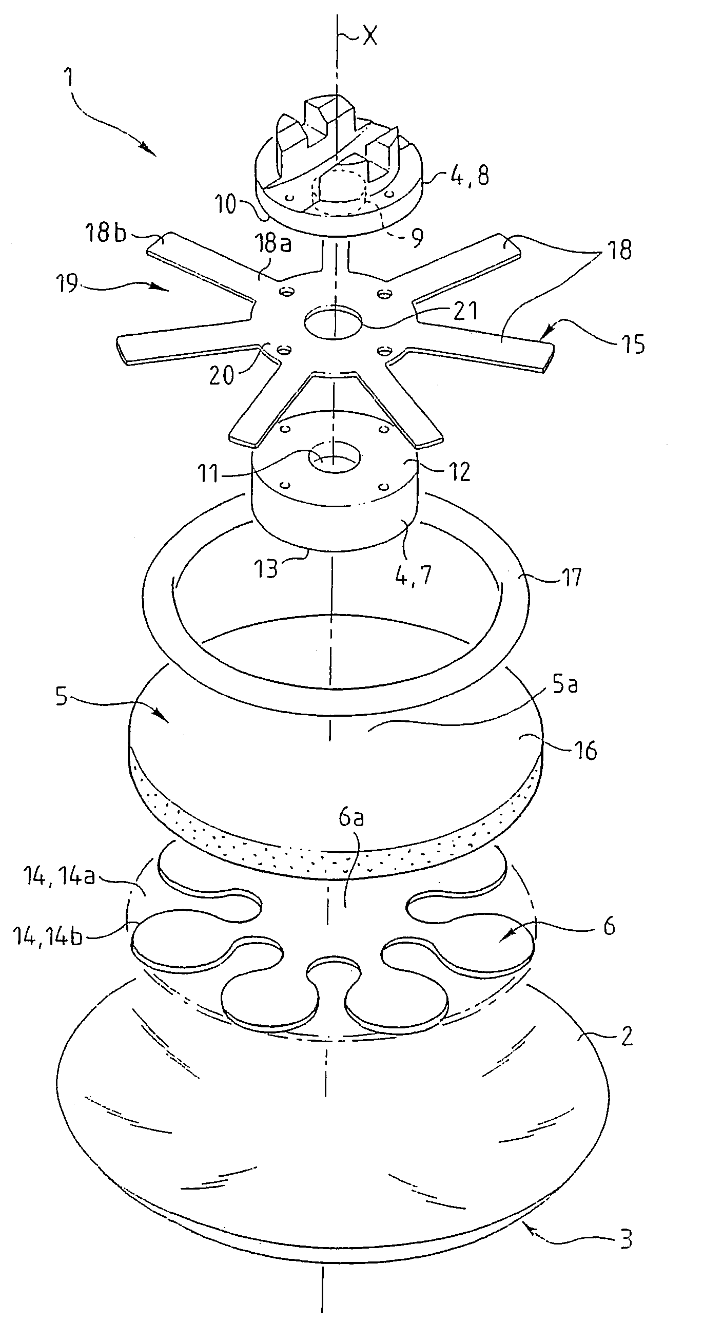
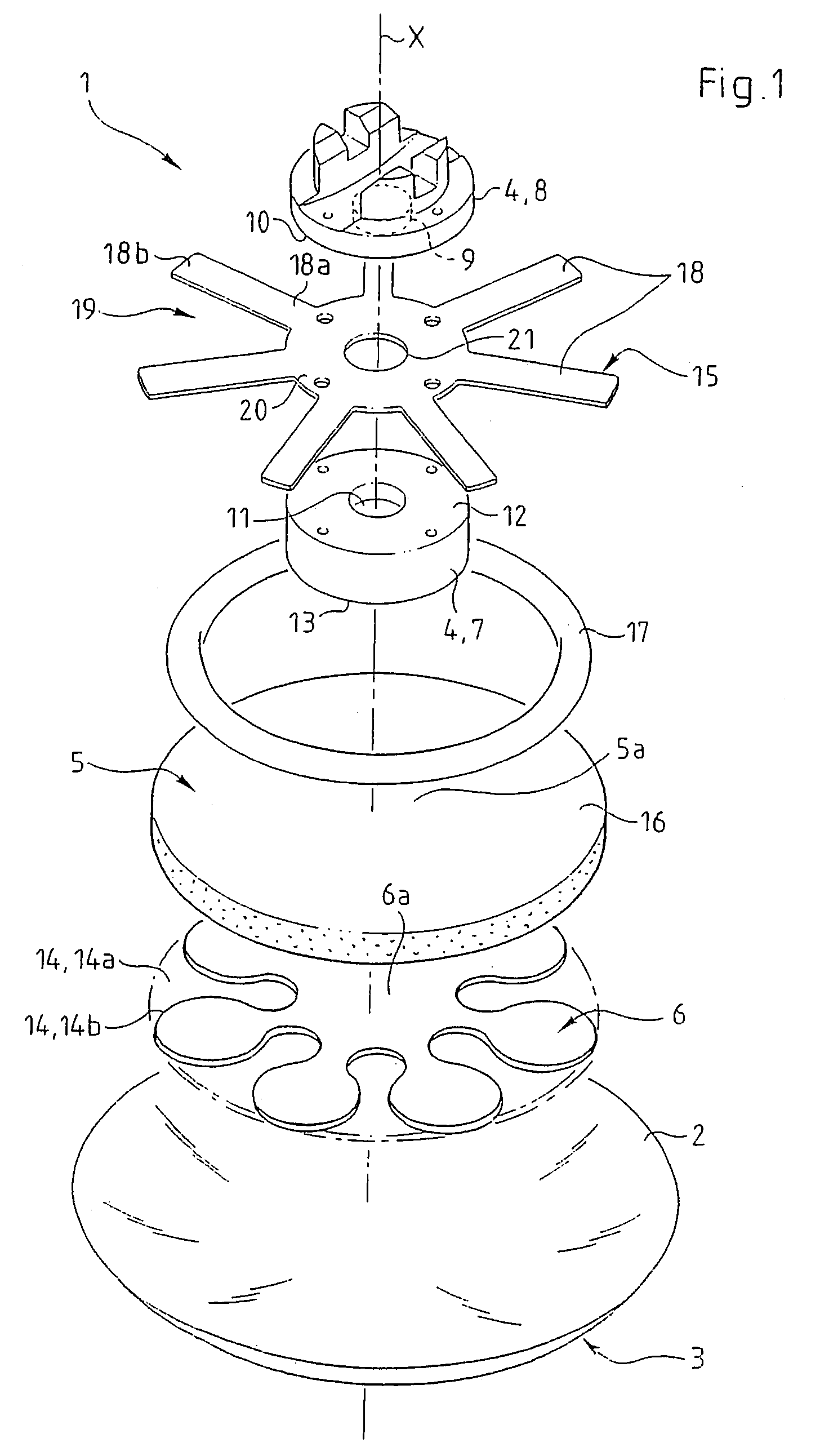
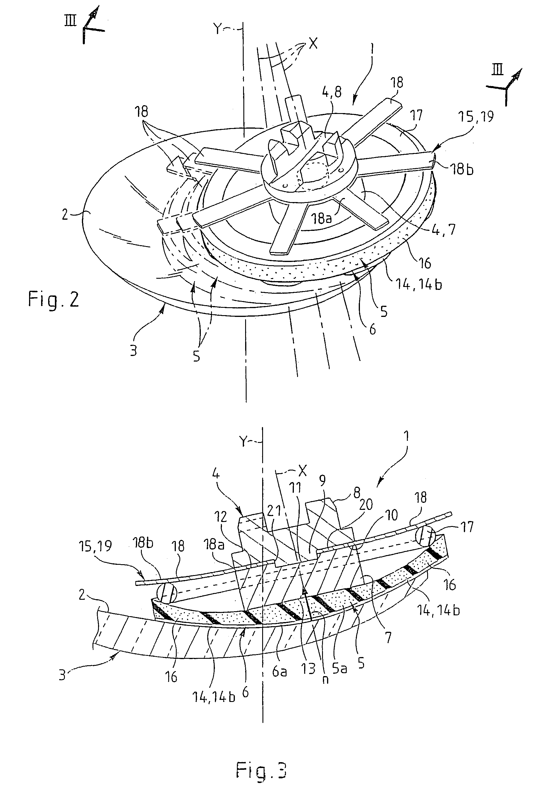
[0055]FIG. 1 shows a tool 1 for surfacing an optical surface 2, in this instance one face of an ophthalmic lens 3. In FIGS. 1 to 3 the optical surface 2 concerned is a concave surface, but it could equally well be a convex surface.

[0056]The tool 1 is formed of a stack of at least three components, namely a rigid component 4, an elastically compressible component 5 and a flexible component 6; these components are respectively referred to hereinafter as the support, the interface and the buffer.

[0057]As may be seen in FIG. 1 in particular, the support 4 comprises two jaws, namely a bottom jaw 7 and a top jaw 8 which are adapted to be stacked and nested one within the other by means of a pin 9 projecting from one face 10 of the top jaw 8 and adapted to lodge in a complementary hole 11 facing it in one face 12 of the bottom jaw 7.

[0058]As may be seen in FIG. 1, the support 4 is a circular cylinder with an axis X of symmetry that defines a longitudinal direction.

[0059]The figure shows th...


PUM


Abstract

A tool for surface treatment of an optical surface, includes a rigid support having a transverse end surface, an elastically compressible interface which is applied against and overlaps the end surface, and a soft buffer designed to be applied against the optical surface and which is pressed against and overlaps at least partly the interface opposite and perpendicular to the end surface. The buffer includes a so-called central part which is located between the end surface and a so-called peripheral part which is located transversely beyond the end surface, elastic return elements connecting the peripheral part to the support.

Description

BACKGROUND OF THE INVENTION[0001]The invention relates to surfacing optical surfaces.[0002]Surfacing means any operation aimed at modifying the surface state of a previously fashioned optical surface. This refers in particular to polishing, softening or depolishing operations aimed at modifying (reducing or increasing) the roughness of the optical surface and / or reducing undulation.[0003]The invention relates to a tool for surfacing an optical surface, which tool comprises a rigid support having a transverse end surface, an elastically compressible interface that is pressed against and covers said end surface, and a flexible buffer adapted to be pressed against the optical surface and which is pressed against and covers at least part of the interface on the side opposite to and in line with said end surface.[0004]To reduce the roughness of the optical surface, the tool is brought into contact with the latter and a sufficient pressure is maintained thereon for the buffer to espouse t...

Claims


Application Information

Patent Timeline
Patent Type & Authority Patents(United States)
IPC IPC(8): B24D17/00B24D99/00B24B13/02B24D7/18B24D9/08
CPCB24D9/08B24B13/02B24B9/06
Inventor HUGUET, JOEL
Owner ESSILOR INT CIE GEN DOPTIQUE
Why Eureka
Try Eureka