Magnetoresistive effect element and magnetic memory device
Active Publication Date: 2006-04-25
SONY CORP
View PDF19 Cites 16 Cited by
Summary
Abstract
Description
Claims
Application Information
AI Technical Summary
This helps you quickly interpret patents by identifying the three key elements:
Problems solved by technology
Method used
Benefits of technology
Benefits of technology
[0024]According to the above-mentioned arrangement of the magnetoresistive effect element of the present invention, since at least one of the pair of ferromagnetic layers contains the amorphous ferromagnetic material of which crystallization temperature is higher than 623 K, heat-resisting temperature can be improved, and hence heat-resisting property of the magnetoresistive effect element can be improved.
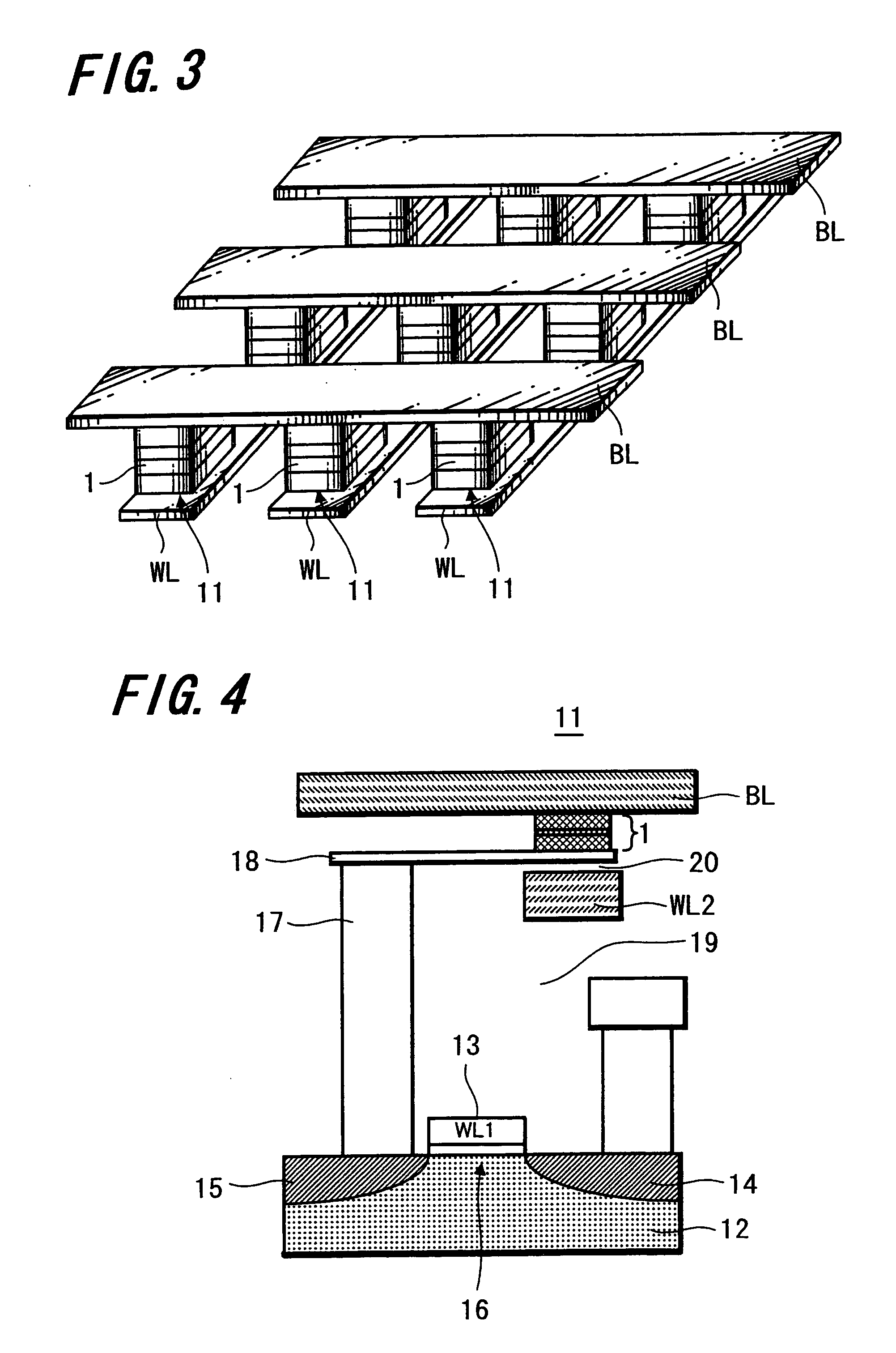
[0025]According to the above-mentioned arrangement of the magnetic memory device of the present invention, since the magnetic memory device includes the magnetoresistive effect element and the word line and the bit line sandwiching the magnetoresistive effect element in the thickness direction and the magnetoresistive effect element is the magnetoresistive effect element of the present invention, heat-resisting property can be improved, and hence a magnetoresistive changing ratio can be suppressed from being lowered due to annealing and excellent read characteristics can be realized.
Problems solved by technology
However, the flash memory encounters with a drawback that its write speed is as slow as the microsecond order.
On the other hand, it has been pointed out that the FRAM has a problem in which it cannot be rewritten so many times.
However, it is known that a TMR element having a ferromagnetic layer made of alloy of Fe-group chemical element such as Fe, Co and Ni is considerably deteriorated in magnetoresistive changing ratio at temperature higher than about 300° C., and therefore it has a problem from a heat-resisting property standpoint.
This magnetoresistive changing ratio may be deteriorated by undesired impurities entered into the ferromagnetic layer or the tunnel barrier layer after components of layers comprising the TMR element have been mutually diffused by heat.
However, when such amorphous alloy is heated at temperature higher than its crystallization temperature, magnetic characteristics, those requested for the TMR element for use with MRAM, such as magnetoresistive changing ratio are deteriorated.
Method used
Image
Click on the blue label to locate the original text in one second.
Reading with bidirectional positioning of images and text.
Examples
experiment 1
(Experiment 1)
[0108]First, magnetic characteristics of magnetic elements having the ferromagnetic layers comprising the ferromagnetic tunnel junction, i.e., the magnetization fixed layer and the magnetization free layer being formed of crystal ferromagnetic materials or amorphous ferromagnetic materials were examined.
[0109]As shown in FIGS. 5 and 6, a structure having a substrate 21 with a word line WL and a bit line BL disposed thereon at a right angle and a TMR element 22 formed at a portion in which these word line WL and bit line BL cross each other was manufactured as a characteristic estimation element TEG (Test Element Group). This TEG has an arrangement in which the TMR element 22 is shaped like an ellipse with a minor axis of 0.5 μm and a major axis of 1.0 μm, terminal pads 23, 24 are respectively formed at both ends of the word line WL and the bit line BL and in which the word line WL and the bit line BL are electrically insulated from each other by insulating films 25, 26...
experiment 2
(Experiment 2)
[0130]The magnetization fixed layer had a synthetic ferrimagnet structure comprising two layers of CoFe and Ru, and the magnetization free layer was formed as a ferromagnetic layer having a composition in which Si or B was added to CoFe. Then, optimum ranges of the added amount of B and the added amount of Si were checked.
[0131]The layer arrangement of the TMR element 22 was selected to be the following layer arrangement (1).
[0132]In the above-described layer arrangement (1), y and z of (Co90Fe10)100−x−ySiyBz indicate composition ratios of atomic % and (Co90Fe10) within the parenthesis shows that Co and Fe have a composition ratio of 90:10. If y=10 atomic % and z=10 atomic % are established, then (Co90Fe10)80Si10B10 is satisfied. This indicates that CoFe alloy having a composition ratio of Co:Fe=90 atomic % :10 atomic % has 80 atomic % and has a compo...
experiment 3
(Experiment 3)
[0165]A magnetization free layer has a synthetic ferrimagnet structure comprising two layers of CoFe and Ru, and a magnetization free layer was formed as a ferromagnetic layer having a composition in which Si and B were added to (Co, Fe). Then, an optimum range of Fe content was checked.
[0166]A TEG was obtained similarly to the sample 10 except that the magnetization free layer has a composition of (Co100-xFex)70Si10B20, further x=0, i.e., a composition of Co70Si10B20 in the layer arrangement (1).
[0167]A TEG was obtained similarly to the sample 42 except that the magnetization free layer has a composition of x=5 atomic %, i.e., a composition of (Co95Fe5)70Si10B20.
[0168]A TEG was obtained similarly to the sample 42 except that the magnetization free layer has a composition of x=10 atomic %, i.e., a composition of (Co90Fe10)70Si10B20.
[0169]A TEG was obtained similarly to the sample 42 except that the magnetization free layer has a composition of x=25 atomic %, i.e., a co...
PUM
Abstract
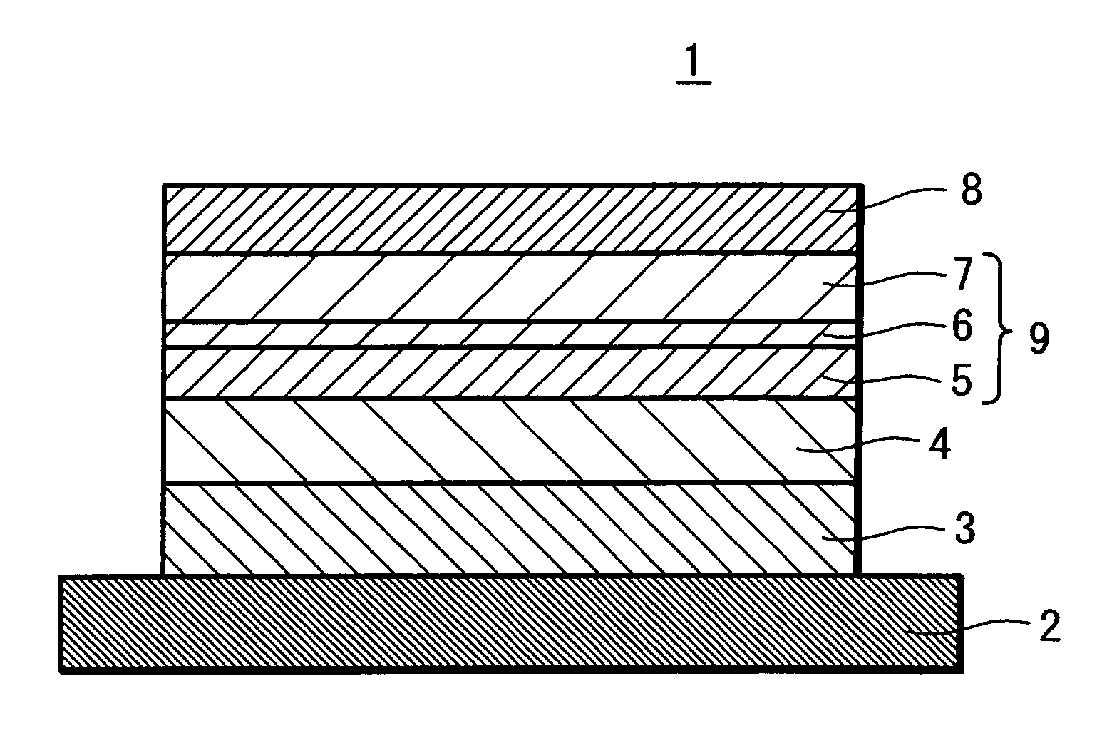
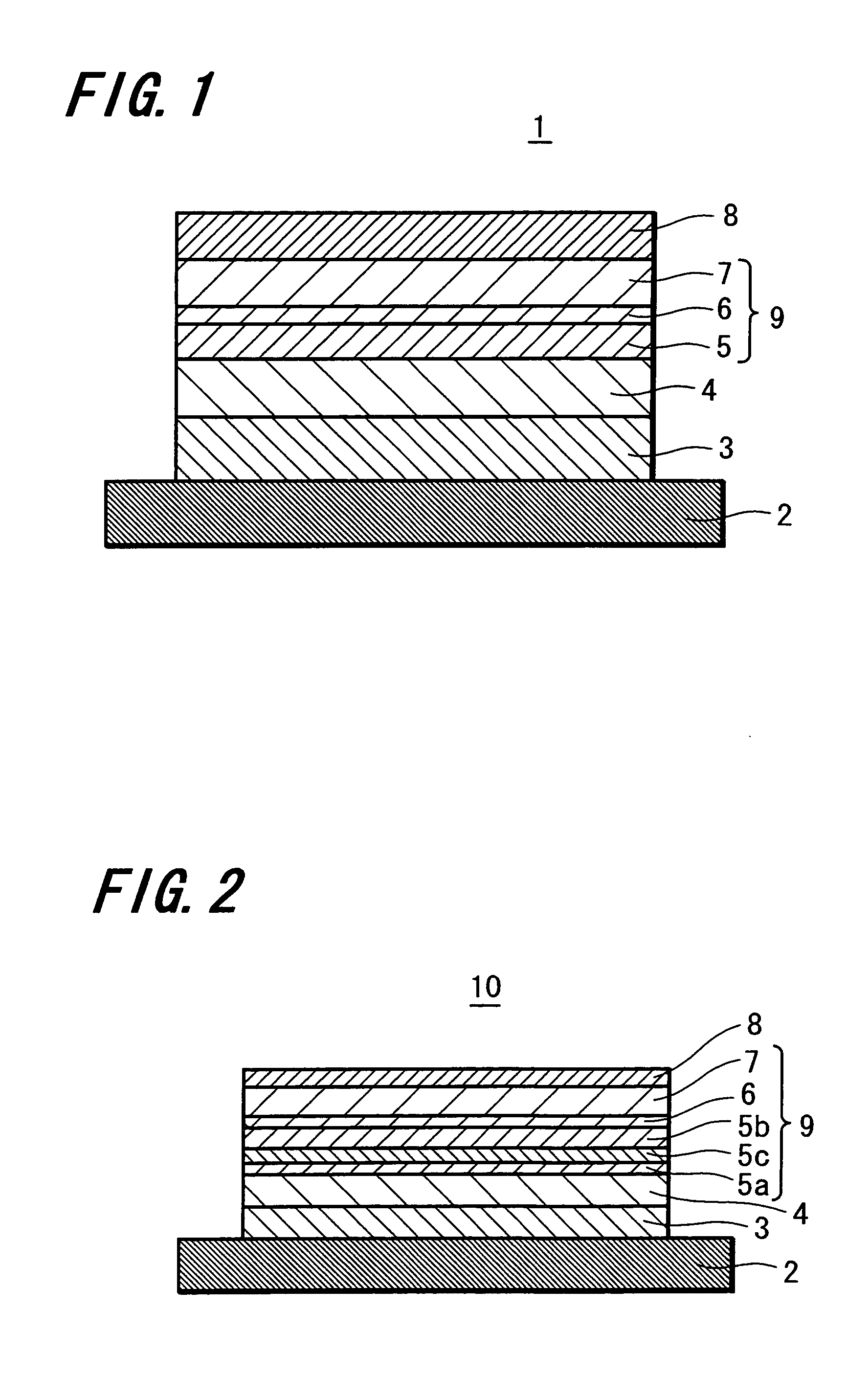
A magnetoresistive effect element may be given satisfactory magnetic characteristics because a deterioration of a magnetoresistive changing rate by annealing can be suppressed and a magnetic memory device includes this magnetoresistive effect element to provide excellent write characteristics. A magnetoresistive effect element has a pair of ferromagnetic layers (magnetization fixed layer 5 and magnetization free layer 7) opposed to each other through an intermediate layer 6 to cause an electric current to flow in the direction perpendicular to the layer surface to obtain a magnetoresistive change. A magnetic memory device comprises the magnetoresistive effect element 1 in which at least one of the pair of ferromagnetic layers 5, 7 contains an amorphous ferromagnetic material whose crystallization temperature is higher than 623 K and bit lines and word lines sandwiching this magnetoresistive effect element and the magnetoresistive effect element in the thickness direction.
Description
BACKGROUND OF THE INVENTION[0001]This application is a 371 of PCT / JP03 / 09825 Aug. 1, 2003[0002]The present invention relates to a magnetoresistive effect element having an arrangement to obtain a magnetoresistive change by causing an electric current to flow in the direction perpendicular to the layer surface and a magnetic memory device including the magnetoresistive effect element.[0003]Information communication devices, in particular, personal small devices such as personal digital assistants are making great spread, elements such as memories and logics comprising information communication devices are requested to have higher performance such as higher integration degree, higher operation speed and lower power consumption. In particular, technologies for making nonvolatile memories become higher in density and larger in storage capacity are progressively increasing their importance as technologies for replacements of hard disk and optical disc that cannot be essentially miniaturi...
Claims
Application Information
Patent Timeline
Application Date:The date an application was filed.
Publication Date:The date a patent or application was officially published.
First Publication Date:The earliest publication date of a patent with the same application number.
Issue Date:Publication date of the patent grant document.
PCT Entry Date:The Entry date of PCT National Phase.
Estimated Expiry Date:The statutory expiry date of a patent right according to the Patent Law, and it is the longest term of protection that the patent right can achieve without the termination of the patent right due to other reasons(Term extension factor has been taken into account ).
Invalid Date:Actual expiry date is based on effective date or publication date of legal transaction data of invalid patent.

