Method for eliminating fuel use during dynamic braking

a dynamic braking and fuel use technology, applied in the direction of mechanical energy handling, motor/generator/converter stopper, dynamo-electric converter control, etc., can solve the problems of slowing down the vehicle, economic unattractive system, engine acting as an energy sink, etc., to reduce the amount of fuel supplied to the engine, reduce the amount of fuel, and increase the maximum braking effort of the vehicle

Inactive Publication Date: 2006-04-25
WESTINGHOUSE AIR BRAKE TECH CORP
View PDF11 Cites 20 Cited by
  • Summary
  • Abstract
  • Description
  • Claims
  • Application Information

AI Technical Summary

Benefits of technology

[0011]The present invention also discloses a method for reducing fuel use and increasing a maximum braking effort of a vehicle when in dynamic braking. The method comprises providing a dynamic braking system comprising an engine, an alternator, a plurality of alternating current electric traction motors, and a plurality of power inverters where each of the traction motors has excitation windings coupled in circuit with a corresponding one of the plurality of power inverters. The method also comprises providing a fuel-free dynamic braking controller and providing a fuel-free dynamic braking transfer switch. The method further comprises placing a vehicle's power level into a dynamic braking mode, activating the fuel-free dynamic braking transfer switch, and allowing the fuel-free dynamic braking controller to command at least one of the inverters to convert DC power produced by a remaining of the inverters into AC power. The method also prevents at least one of the traction motors from generating and consuming power, rotates the alternator and the engine to produce power, and reduces the amount of fuel supplied to the engine.
[0012]The present invention further discloses another preferred method for reducing fuel use and increasing a maximum braking effort of a vehicle when in dynamic braking. This method comprises providing a dynamic braking system comprising an engine, an alternator, a plurality of alternating current electric traction motors, and a plurality of power inverters where each of the traction motors has excitation windings coupled in circuit with a corresponding one of the plurality of power inverters. Also provided are a fuel-free dynamic braking controller, a fuel-free dynamic braking inverter, and a fuel-free dynamic braking contactor. The method also places a vehicle's power level into a dynamic braking mode and activates the fuel-free dynamic braking contactor. The method further allows the fuel-free dynamic braking controller to command the fuel-free dynamic braking inverter to convert DC power produced by the plurality of power inverters into AC power. The method also rotates at least one of the alternator and the engine to produce power, and reduces the amount of fuel supplied to the engine.

Problems solved by technology

Though it would be highly advantageous to store the energy produced by the traction motors in DB for later use, the high capital cost of the necessary energy storage components has heretofore rendered such a system economically unattractive.
Because the compressed and heated air is discarded to the environment, the engine acts as an energy sink when compression braking is activated and slows the vehicle.
When a locomotive or off highway vehicle with AC traction motors slows in Dynamic Braking, the engine continues to consume fuel to meet the electrical needs of the vehicle.
In other words, if the rotation of the wheel slows or stops and sliding ensues, the vehicle will take longer to stop.

Method used


Image

  • Method for eliminating fuel use during dynamic braking
  • Method for eliminating fuel use during dynamic braking
  • Method for eliminating fuel use during dynamic braking

Examples


Embodiment Construction

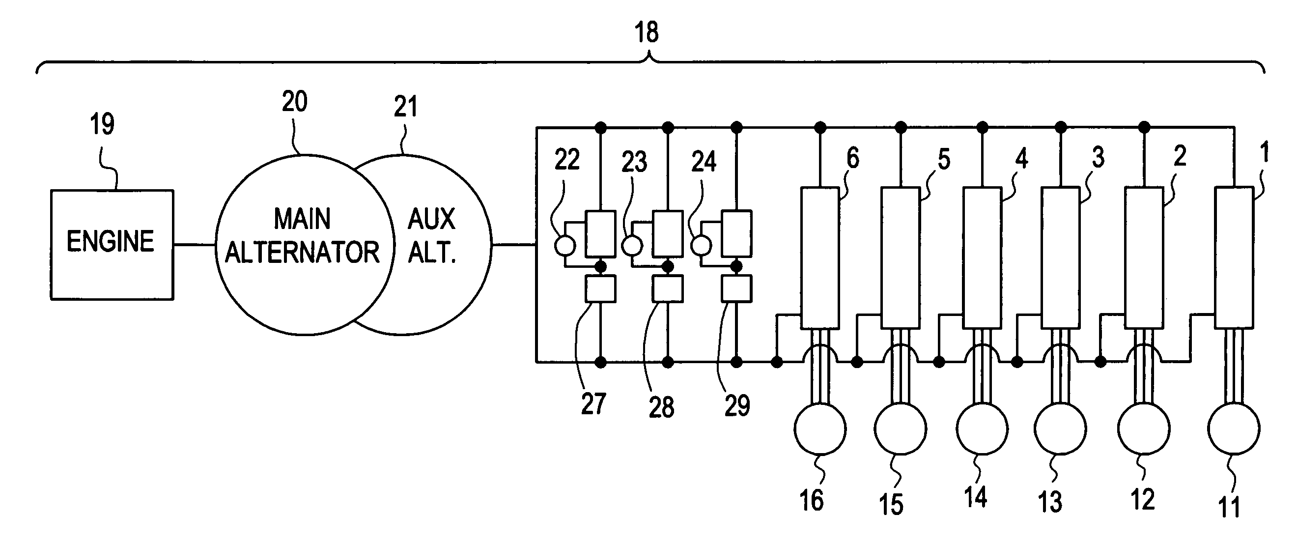
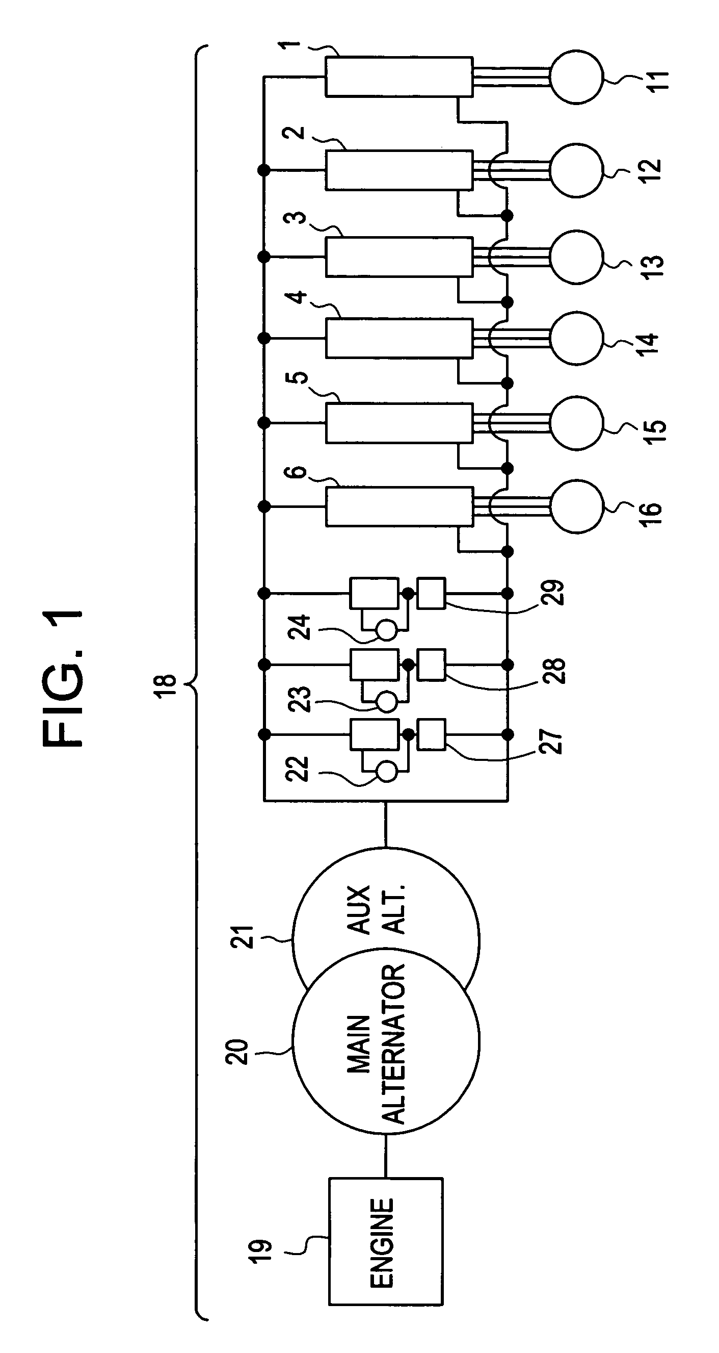
[0020]With reference to the figures, exemplary embodiments of the invention will now be described. Although this invention is disclosed specific to a dynamic braking system on a locomotive, this invention is applicable to other dynamic braking systems in general, for example those used on road or off-highway vehicles with AC traction motors and traction motor inverters. Additionally this invention is disclosed as being used with a vehicle having six traction motors. This invention is also applicable to vehicles having other than six traction motors.

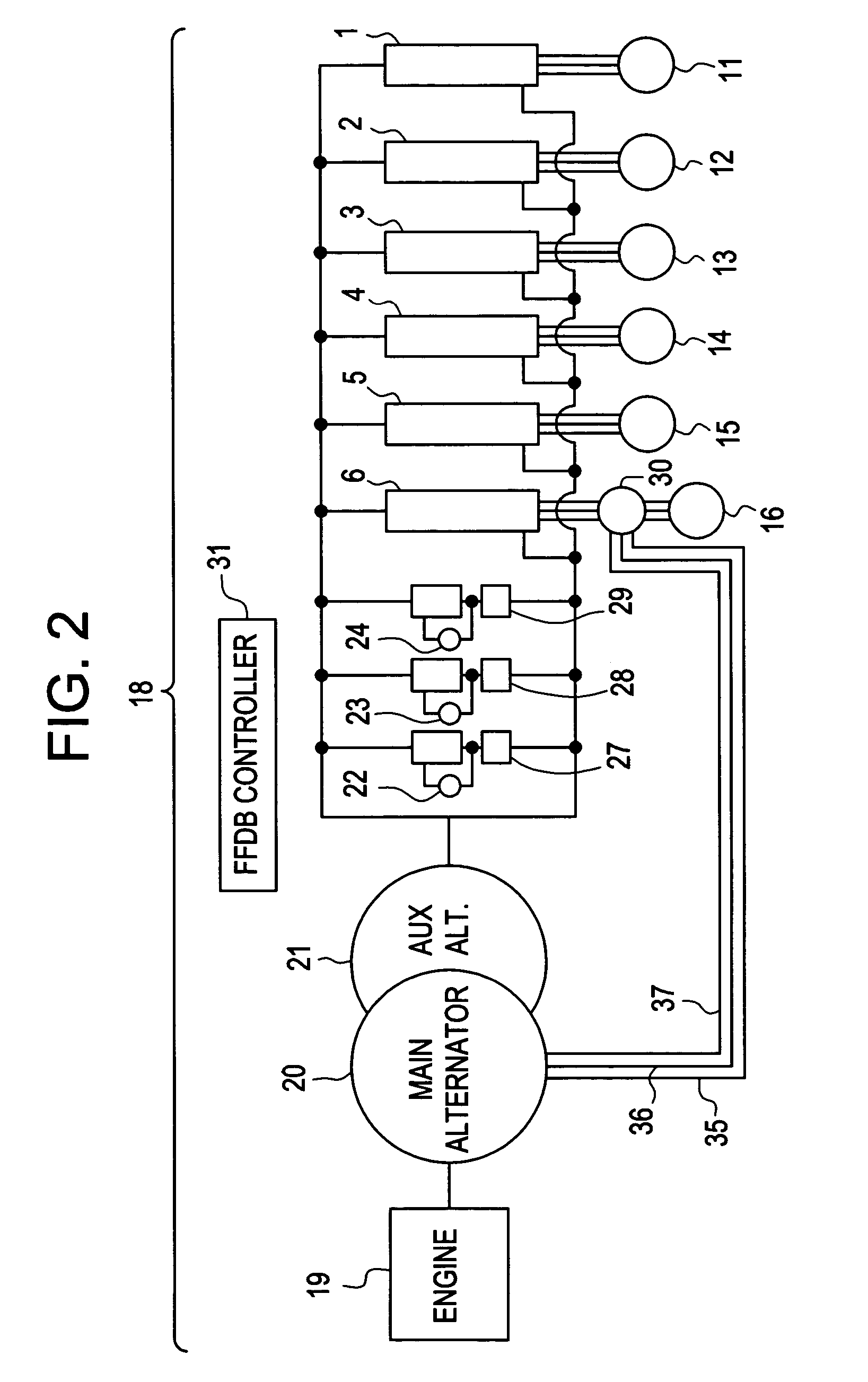
[0021]FIG. 1 is an exemplary simplified block diagram of a locomotive and several components common in a prior art dynamic braking system, and FIG. 2 is an exemplary more detailed block diagram of a prior art AC locomotive power transmission and dynamic braking system. In FIG. 1, an AC locomotive 18 in motoring operation produces AC power where a main or traction motor alternator 20 is turned by a diesel engine 19. The traction motor alte...


PUM


Abstract

A method for reducing engine fuel consumption of an electro-motive vehicle during braking, the method including steps for providing an engine for the vehicle, generating primary electric power at a primary electric power generator connected to the engine, generating primary electric power at a secondary electric power generator connected to the engine, operating a plurality of electric traction motors each coupled in driving relationship to a respective one of a plurality of driven wheels to propel the vehicle during motoring operations and to generate electricity upon braking operations of the vehicle, electrically connecting a braking switch between the traction motors and the primary electric power generator, applying braking, closing the braking switch, and transmitting power generated by the traction motors to the primary electric power generator to operate as a motor to rotate the engine and drive the secondary electric power generator to power the auxiliary equipment without fueling the engine.

Description

[0001]This is a continuation of U.S. Ser. No. 10 / 160,867, filed on May 31, 2002 now U.S. Pat. No. 6,803,734, from which Applicant claims priority.BACKGROUND OF THE INVENTION[0002]This invention relates to a braking system, and more specifically, to a system and method for eliminating fuel use and increasing the maximum braking effort of a particular kind of rail locomotive or off-highway vehicle while in a dynamic braking state.[0003]Diesel electric locomotives generally have two means for slowing a train, where a train consists of at least one locomotive and one rail car, when a need arises. A first means is to apply air brakes that when engaged apply brake shoes to the wheels of a locomotive and / or rail cars to convert the kinetic energy of the train's motion into heat in the wheels, brake shoes and rails. A second means is referred to as “Dynamic Braking” (or DB). In dynamic braking, the electric traction motors of a locomotive are used to slow the train by applying tractive effo...

Claims


Application Information

Patent Timeline
Patent Type & Authority Patents(United States)
IPC IPC(8): H02K17/32H02K23/68H02K27/30H02K7/10H02P3/00H02P3/14
CPCH02P3/14
Inventor KUMAR, AJITH KUTTANNAIRVALENTINE, PETER LORING
Owner WESTINGHOUSE AIR BRAKE TECH CORP
Why Eureka
Try Eureka