
Hysteretic controlled switch regulator with fixed off time

a switch regulator and fixed off time technology, applied in the direction of automatic control, process and machine control, instruments, etc., can solve the problems of high noise generated by users of electronic equipment, inability to control the switching frequency, so as to keep the operation of the switch regulator quiet and low overhead

Active Publication Date: 2006-04-25
TEXAS INSTR INC
View PDF3 Cites 16 Cited by
  • Summary
  • Abstract
  • Description
  • Claims
  • Application Information

AI Technical Summary

Benefits of technology

The present invention provides a system for a switched regulator with an adjustable operating frequency range. This allows the regulator to be adjusted based on the supply voltage, while keeping the operation relatively quiet and at a low overhead. The technical effects of this invention include improved flexibility, efficiency, and reduced noise.

Problems solved by technology

A problem that can arise with hysteretic controlled switching regulators is that when it is driving a light load, the switching frequency may enter the range of human hearing (i.e., less than 20 kilo-hertz).
This may then lead inductive components connected to the switching regulator to generate audible noise.
The noise generated can be highly undesirable by users of the electronic equipment, and therefore is typically unwanted.
By fixing the switching frequency of the switching regulator, it would be impossible for the switching frequency to drift off into hearing range.
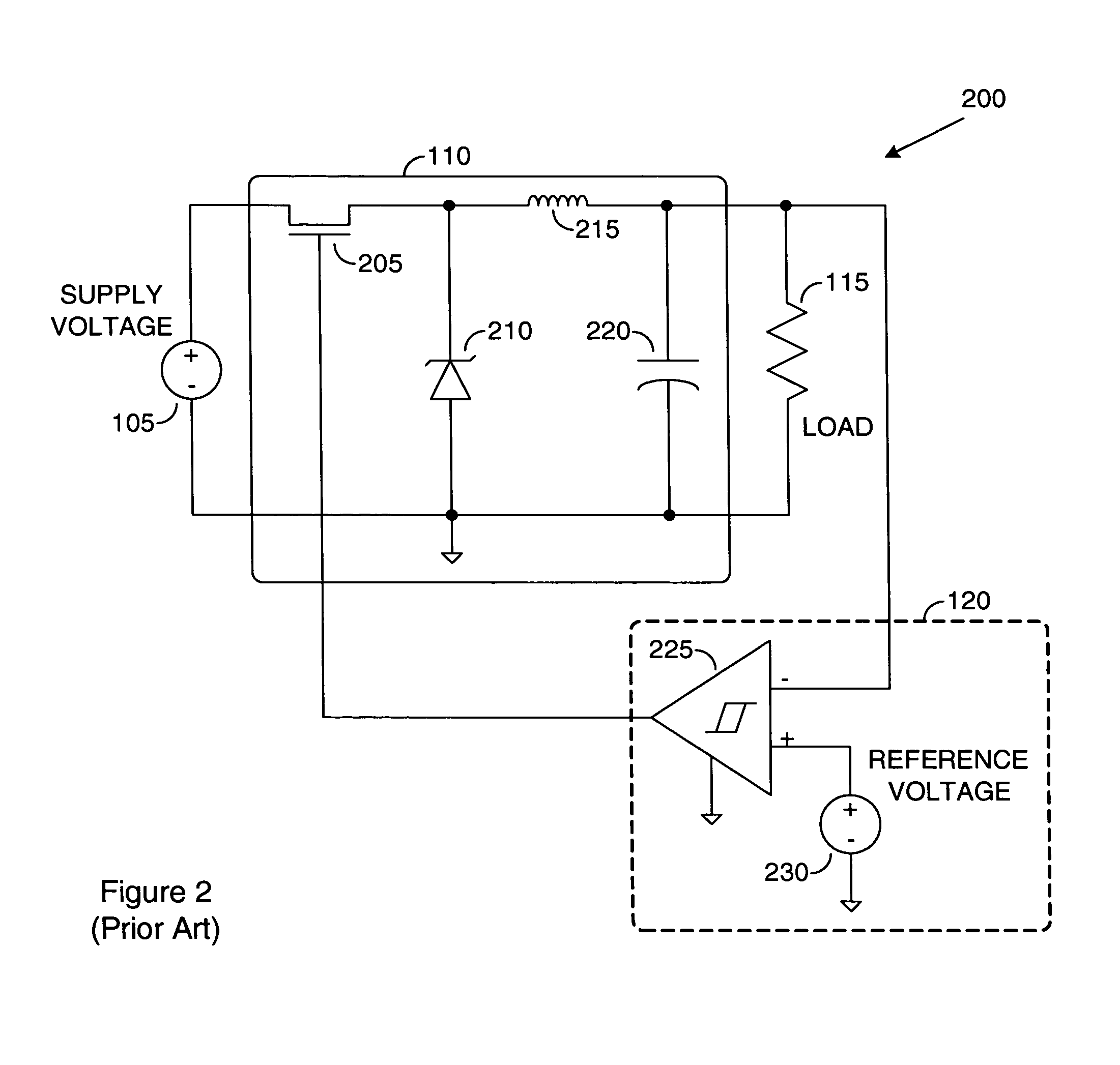
One disadvantage of the prior art is that the forced off time and the fixed frequency requires a higher minimum supply voltage due to the fact that there is a maximum ratio for on time to off time.
A second disadvantage of the prior art is that it operates at a fixed frequency and cannot adjust its operating frequency dynamically.

Method used


Image

  • Hysteretic controlled switch regulator with fixed off time
  • Hysteretic controlled switch regulator with fixed off time
  • Hysteretic controlled switch regulator with fixed off time

Examples


Embodiment Construction

[0022]The making and using of the presently preferred embodiments are discussed in detail below. It should be appreciated, however, that the present invention provides many applicable inventive concepts that can be embodied in a wide variety of specific contexts. The specific embodiments discussed are merely illustrative of specific ways to make and use the invention, and do not limit the scope of the invention.

[0023]The present invention will be described with respect to preferred embodiments in a specific context, namely a circuit for producing regulated DC voltages. The invention may also be applied, however, to other applications, such as projects requiring voltage regulators.

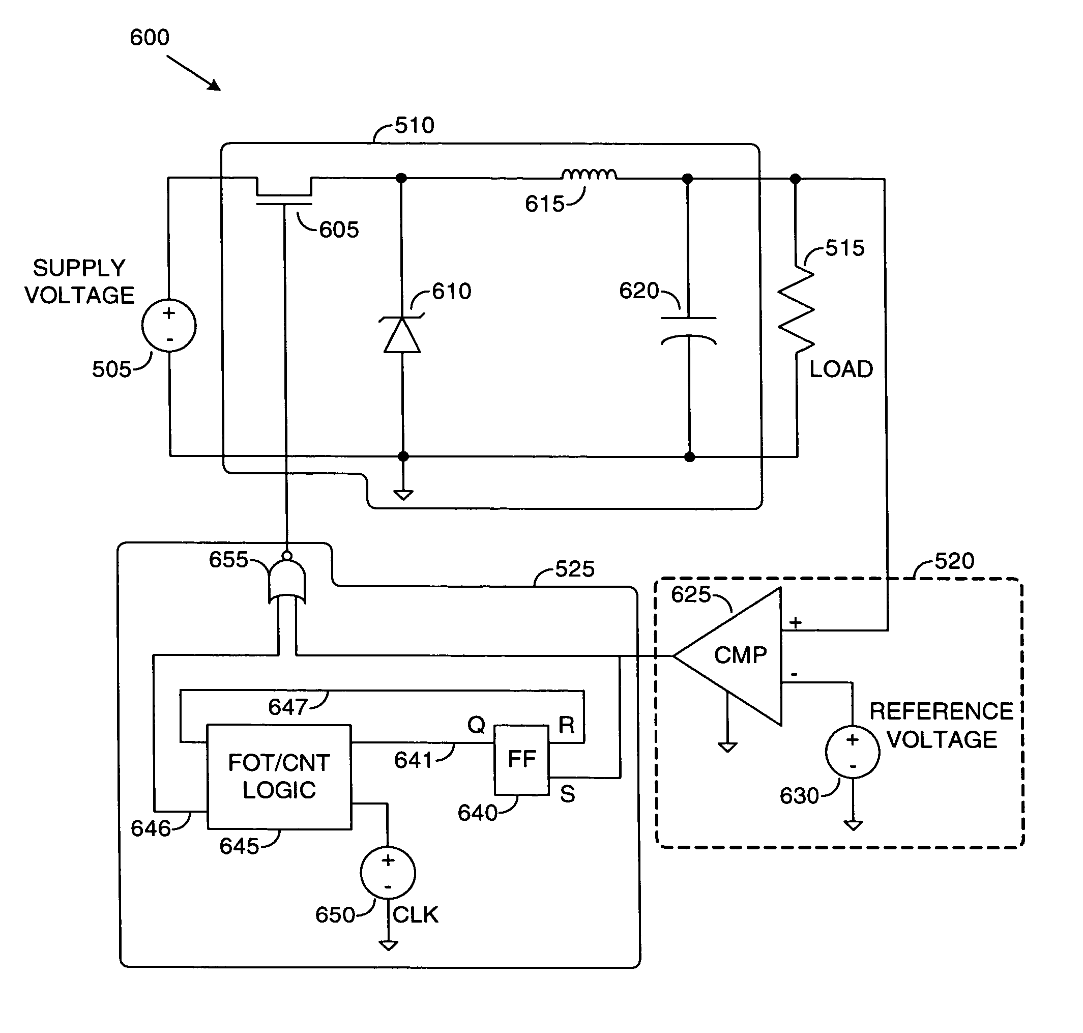
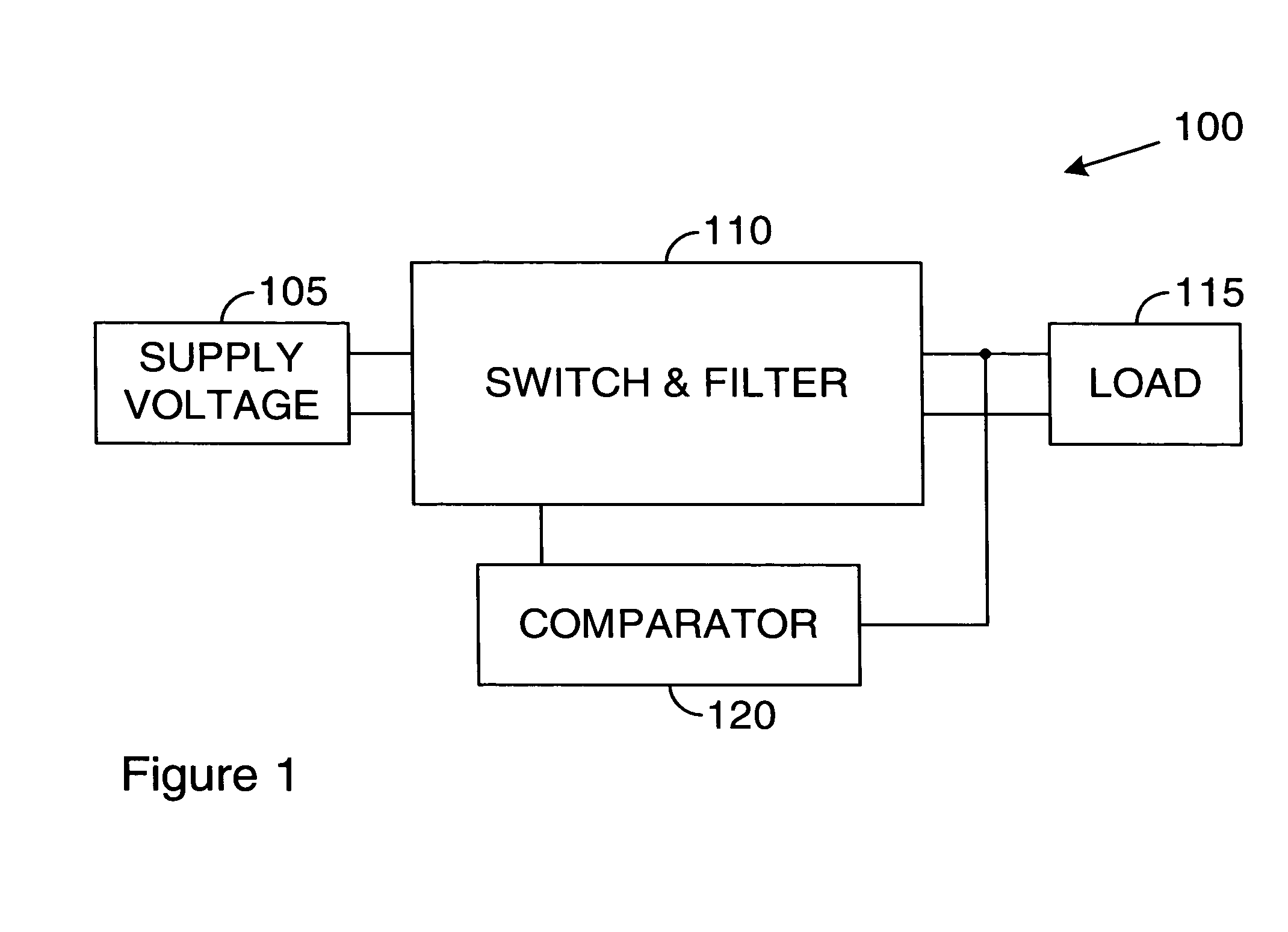
[0024]With reference now to FIG. 1, there is shown a diagram illustrating a high-level view of a hysteretic controlled switch regulator (HCSR) 100. The HCSR 100 may be divided into four distinct parts: a supply voltage 105, a switch and filter block (SFB) 110, a load 115, and a comparator 120. The supply vo...


PUM


Abstract

System for providing a switched regulator with an adjustable operating frequency range. A preferred embodiment comprises a voltage supply and a load, a switch and filter block (SFB) (such as the SFB 510), a comparator (such as the comparator 520), and a fixed off time logic (FOTL) (such as the FOTL 525). The comparator compares an output voltage with a reference voltage. When the output voltage is equal to or exceeds the reference voltage, the comparator asserts a value on a signal line to the FOTL. The FOTL then shuts down the SFB for a specified period of time. During the off time, the output voltage decays. After the specified period of time expires, the SFB is turned back on and the output voltage can recharge. The duration of time that the SFB remains on is a function of the supply voltage, thus permitting an adjustable operating frequency.

Description

[0001]This application claims the benefit of U.S. Provisional Application No. 60 / 486,391, filed on Jul. 11, 2003, entitled “Hysteric Controlled Switch Regulator with Fixed Off Time,” which application is hereby incorporated herein by reference.TECHNICAL FIELD[0002]The present invention relates generally to a system for providing regulated voltages, and more particularly to a system for providing a regulator with an adjustable operating frequency range.BACKGROUND[0003]A hysteretic controlled switching regulator is typically used to provide a constant and predetermined output voltage to a load. Input to the hysteretic controlled switching regulator may typically be a fluctuating voltage source. As an example, a commonly used application of a hysteretic controlled switching regulator would be in the conversion of rectifier output in a standard AC adaptor (which can have a significant amount of ripple) to stable DC output that can be used in a wide variety of electronic equipment, such ...

Claims


Application Information

Patent Timeline
Patent Type & Authority Patents(United States)
IPC IPC(8): G05F1/40H02M3/156
CPCH02M3/156
Inventor XU, JINGWEILATA, ZBIGNIEW J.GROSE, WILLIAM E.
Owner TEXAS INSTR INC
Learn More