Flyback converter providing simplified control of rectifier MOSFETS when utilizing both stacked secondary windings and synchronous rectification

a flyback converter and secondary winding technology, applied in the direction of electric variable regulation, process and machine control, instruments, etc., can solve the problems of insufficient understanding of the exact operation of self-driven synchronous rectifiers, inability to utilize stacked winding configuration for generating more than one voltage output, and inability to achieve self-driven synchronous rectifiers. precise operation, the effect of simplifying the control circuit and reducing the complexity of multiple control voltages

Active Publication Date: 2010-03-16
CIENA
View PDF4 Cites 11 Cited by
  • Summary
  • Abstract
  • Description
  • Claims
  • Application Information

AI Technical Summary

Benefits of technology

[0012]In various exemplary embodiments, the present invention eliminates the complexity of multiple control voltages by arranging synchronous rectifier MOSFETs in such a manner that they operate with a common source potential while still providing for the use of a stacked output winding in a flyback converter topology. With a common source potential, a single rectifier control voltage can be used to operate the rectifiers for multiple outputs greatly simplifying the control circuit. The MOSFETs are arranged to provide a simple form of synchronous rectification. Advantageously, the present invention maintains the inherent simplicity of the flyback design while enabling designs with well-regulated multiple voltage outputs and the efficiency benefits of synchronous rectification.
[0013]The invention simplifies the gate drive requirements when using both a stacked output winding configuration and synchronous rectification in the flyback converter topology. In particular, when relying on a self driven synchronous rectification arrangement, only a single control winding is required to operate all of the synchronous rectifiers. This reduces the cost and size of the transformer by enabling the use of a lower pin count winding bobbin. Furthermore the application of a “commutation assist” inductor to the self-driven variant of the invention eliminates the reliance on the poorly controlled transformer leakage inductance, thus resulting in a design which is less sensitive to variations in the transformer construction improving the design yield and reliability. In summary the resulting design achieves improved performance while maintaining a minimum size and cost.
[0014]In an exemplary embodiment of the present invention, a dual-output flyback converter with stacked secondary windings and synchronous rectifiers arranged to provide a common reference for rectifier gate control includes a transformer with a first and second stacked secondary winding, a first synchronous rectifier connected to the first stacked secondary winding, and a second synchronous rectifier connected to the second stacked secondary winding, wherein the first and second synchronous rectifiers are arranged to provide a common reference for gate control of the first and second synchronous rectifier. A single rectifier control voltage is utilized to operate the first and second rectifiers. Optionally, the first and second rectifiers include a MOSFET. The dual-output flyback further includes a control winding on the transformer operable to control the first and second synchronous rectifiers, and the dual-output flyback converter is self driven in a forced continuous-current mode of operation. The dual-output flyback converter further includes a commutation assist inductor in the path of the control winding, wherein the commutation assist inductor minimizes leakage inductance. The dual-output flyback further includes stacked output capacitors.

Problems solved by technology

However, this does not utilize a stacked winding configuration for generating more than one voltage output while applying synchronous rectification to all of the outputs.
Thus the complexity of the rectifier control function is substantially increased due to the need for multiple MOSFET control voltages; at the very least these voltages must be derived through some form of level shifting and / or multiple control voltage windings.
Furthermore, a review of the literature shows that the exact operation of self-driven synchronous rectifier, forced continuous-current mode (CCM), flyback converters is not well understood.
For example, Zhang et al. state in “Design Considerations and Performance Evaluations of Synchronous Rectification in Flyback Converters”, IEEE Transactions On Power Electronics, Vol. 13, No. 3, May 1998, that the self driven mode is not possible in a flyback converter.
However, as pointed out in Xie et al., “Current-Driven Synchronous Rectification Technique For Flyback Topology”, IEEE 32nd Annual Power Electronics Specialists Conference, Volume 1, 2001, without sufficient leakage inductance in the power carrying windings of the transformer the MOSFETs in a self driven synchronously rectified converter will fail to commutate properly.
The failure to commutate results in simultaneous current flow in both the primary and secondary windings of the flyback transformer which in turn typically results in a catastrophic failure of one or more of the MOSFET switches.

Method used


Image

  • Flyback converter providing simplified control of rectifier MOSFETS when utilizing both stacked secondary windings and synchronous rectification
  • Flyback converter providing simplified control of rectifier MOSFETS when utilizing both stacked secondary windings and synchronous rectification
  • Flyback converter providing simplified control of rectifier MOSFETS when utilizing both stacked secondary windings and synchronous rectification

Examples


Embodiment Construction

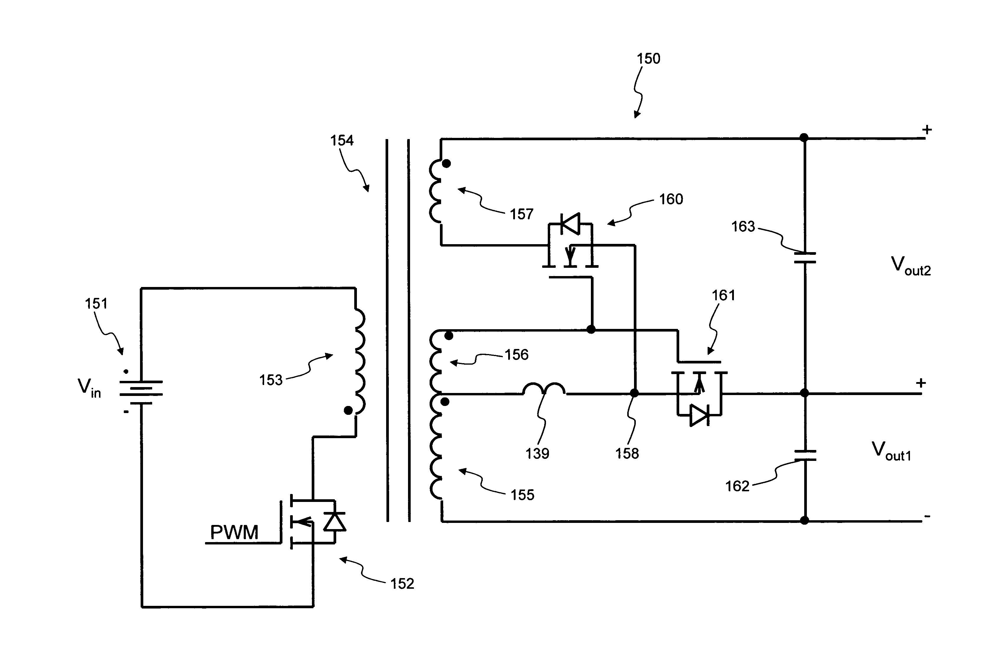
[0029]In various exemplary embodiments, the present invention eliminates the complexity of multiple control voltages by arranging synchronous rectifier MOSFETs in such a manner that they operate with a common source potential while still providing for the use of a stacked output winding in a flyback converter topology. With a common source potential, a single rectifier control voltage can be used to operate the rectifiers for multiple outputs greatly simplifying the control circuit. The MOSFETs are arranged to provide a simple form of synchronous rectification. Advantageously, the present invention maintains the inherent simplicity of the flyback design while enabling designs with well-regulated multiple voltage outputs and the efficiency benefits of synchronous rectification.

[0030]The invention simplifies the gate drive requirements when using both a stacked output winding configuration and synchronous rectification in a flyback converter. In particular, when relying on a self driv...


PUM


Abstract

The present invention provides methods and systems for a flyback converter arranged with synchronous rectifier MOSFETS in such a manner that they operate with a common source potential while still providing for the use of a stacked output winding. With a common source potential, a single rectifier control voltage can be used to operate the rectifiers for multiple outputs greatly simplifying the control circuit. Advantageously, the present invention maintains the inherent simplicity of the flyback design while enabling designs with well-regulated multiple voltage outputs and the efficiency benefits of synchronous rectification.

Description

FIELD OF THE INVENTION[0001]The present invention relates generally to a power switching flyback converter circuit. More specifically, the present invention provides a flyback converter with simplified control of rectifier MOSFETS when utilizing both stacked secondary windings and synchronous rectification.BACKGROUND OF THE INVENTION[0002]A switching power converter transfers power from an input supply voltage source to one or more output voltage supply sources. In general, this is done by using the input supply to transfer energy to a storage element and then transferring the stored energy in a controlled manner to the output. In most commonly used switching power converters the energy is stored in some form of inductor; the exception being a class of converter known as a “charge pump” which stores energy in a capacitor. There are a variety of different switching converter topologies (circuits) such as buck, flyback, forward, sepic, half bridge, full bridge, and the like with the f...

Claims


Application Information

Patent Timeline
Patent Type & Authority Patents(United States)
IPC IPC(8): H02M3/335
CPCH02M3/33592Y02B70/1475Y02B70/10
Inventor WINGROVE, MICHAEL J.MALECKI, DAVID R.
Owner CIENA
Why Eureka
Try Eureka