Electromagnetic starter switch

a starter switch and electric technology, applied in the direction of engine starters, machines/engines, relays, etc., can solve the problem of abnormal temperature rise of resistors, and achieve the effect of preventing abnormal temperature rises of resistors

Active Publication Date: 2006-04-25
MITSUBISHI ELECTRIC CORP
View PDF4 Cites 45 Cited by
  • Summary
  • Abstract
  • Description
  • Claims
  • Application Information

AI Technical Summary

Benefits of technology

[0010]Using an electromagnetic starter switch according to the present in

Problems solved by technology

In an electromagnetic starter switch having the above configuration, after the auxiliary movable contact comes into contact with the auxiliary fixed contact, rotating the armature at low speed to intermesh the pinion fixed to the shaft of the motor with the ring gear, electric current from the battery should flow through the armature of t

Method used


Image

  • Electromagnetic starter switch
  • Electromagnetic starter switch
  • Electromagnetic starter switch

Examples


embodiment 1

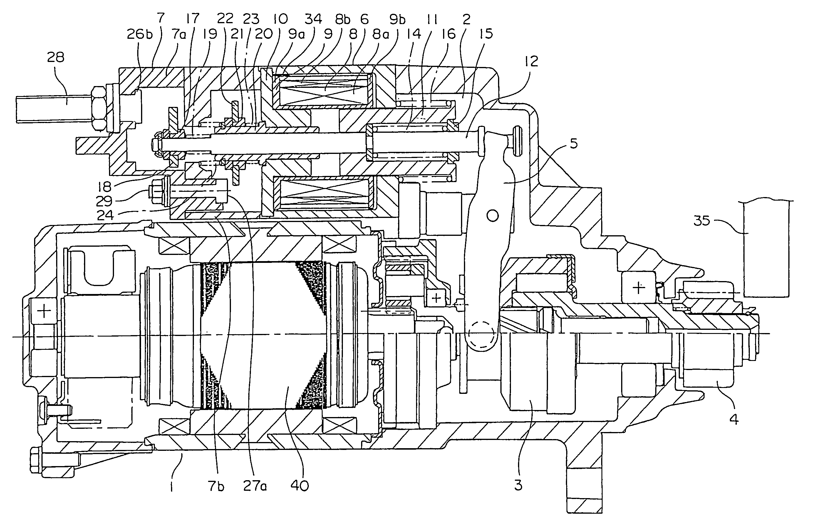
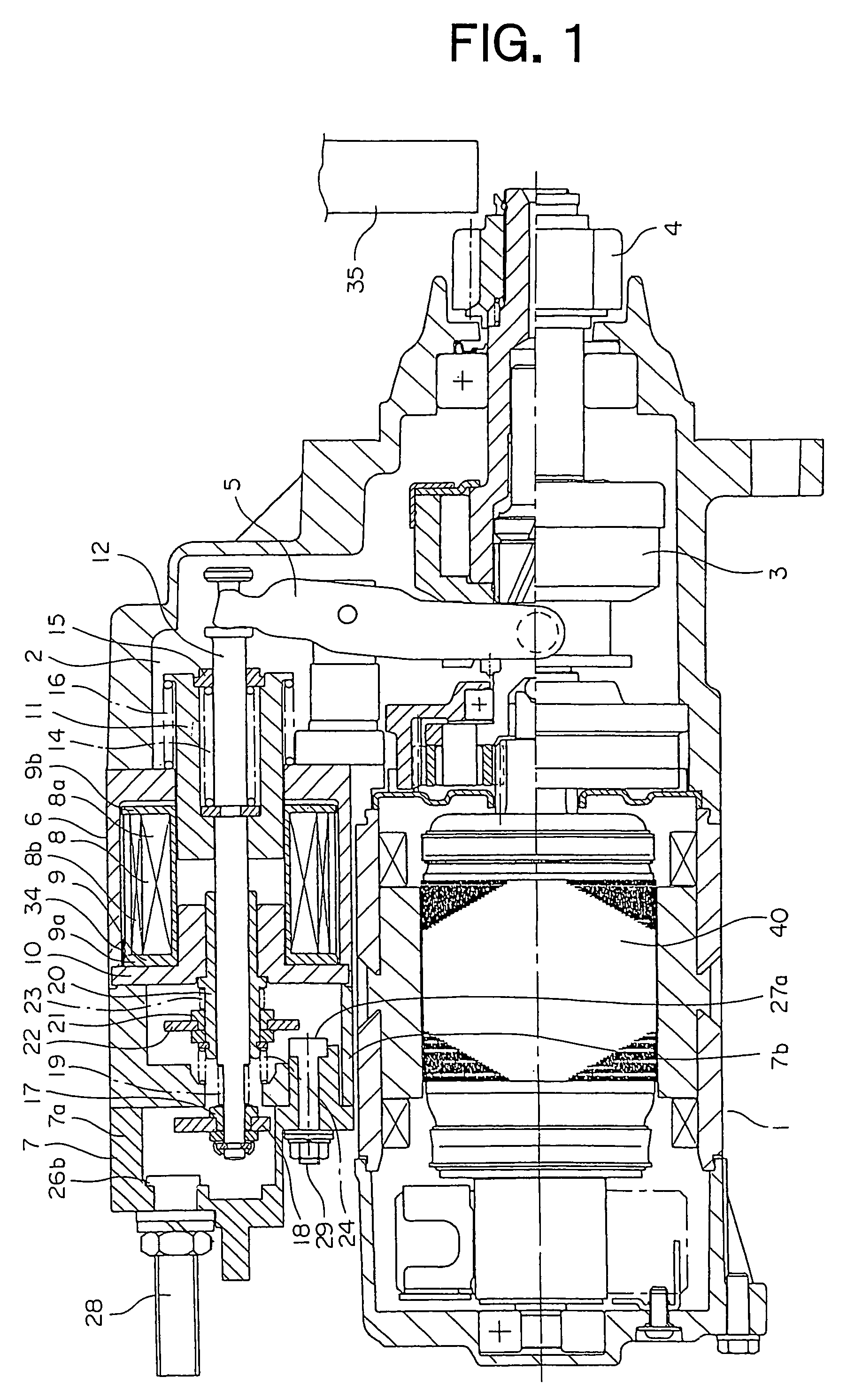
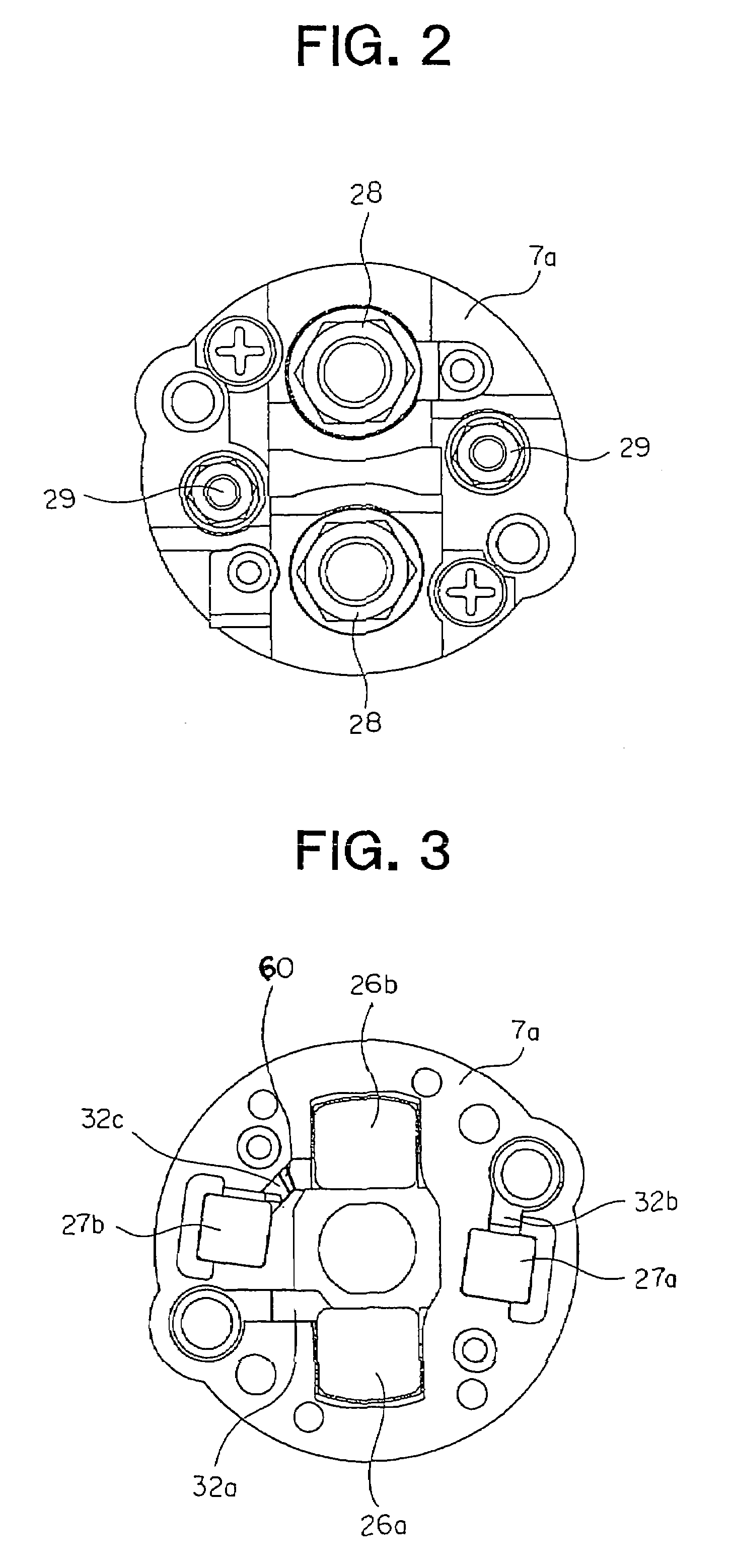
[0021]FIG. 1 is a cross section showing a starter according to Embodiment 1 of the present invention is installed, FIG. 2 is a diagram showing a main switch cover 7a from FIG. 1 when viewed from a left side, and FIG. 3 is a rear end elevation showing the main switch cover 7a in FIG. 2. Moreover, the cross section in the electromagnetic starter switch (hereinafter abbreviated to “electromagnetic switch”) 2 in FIG. 1 is a cross section parallel to central axes of a second main fixed contact 26b and a first auxiliary fixed contact 27a.

[0022]This starter includes: a motor 1; an electromagnetic switch 2 for switching on and off passage of electric current to the motor 1; a clutch 3 that is movable axially along a shaft of the motor 1; a pinion 4 linked to the clutch 3 and rotating with the clutch 3; and a lever 5 rotatably disposed between the electromagnetic switch 2 and the clutch 3.

[0023]In the electromagnetic switch 2, a switch cover 7 is connected to an opening portion of a cylindr...

embodiment 2

[0046]FIG. 8 is an electrical circuit diagram for an electromagnetic switch in which a coil 50 is not separated into a primary coil and a secondary coil.

[0047]In the case of this configuration, a resistor 34 is connected between a first main fixed contact 26a and a first auxiliary fixed contact 27a, and an electric current fuse 60 is disposed between the second main fixed contact 26b and the second auxiliary fixed contact 27b, this embodiment also having similar effects to those of Embodiment 1.

[0048]Of course, as shown in FIG. 9, the resistor 34 may also be connected between the second main fixed contact 26b and the second auxiliary fixed contact 27b, and the electric current fuse 60 disposed between the first main fixed contact 26a and the first auxiliary fixed contact 27a.


PUM


Abstract

An electromagnetic starter switch in which a voltage from a power source is depressed by a resistor and applied to a motor by an auxiliary movable contact coming into contact with a first auxiliary fixed contact and a second auxiliary fixed contact before a pinion intermeshes with a ring gear, and the voltage from the power source is subsequently applied to the motor without modification by the main movable contact also coming into contact with a first main fixed contact and a second main fixed contact after the pinion intermeshes with the ring gear, wherein: a resistor is disposed between the first main fixed contact and the first auxiliary fixed contact or between the second main fixed contact and the second auxiliary fixed contact; and an electric current fuse is disposed between the second main fixed contact and the second auxiliary fixed contact or between the first main fixed contact and the first auxiliary fixed contact.

Description

BACKGROUND OF THE INVENTION[0001]1. Field of the Invention[0002]The present invention relates to an electromagnetic starter switch for starting an internal combustion engine by means of a pinion driven by a motor.[0003]2. Description of the Related Art[0004]Conventionally, in electromagnetic starter switches, in order to control action of a motor during starting so as to be divided into two phases, there is provided: a main fixed contact; a main movable contact coming into contact with the main fixed contact; an auxiliary fixed contact; and an auxiliary movable contact coming into contact with the auxiliary fixed contact, a resistor being installed in series in a circuit formed when the auxiliary movable contact comes into contact with the auxiliary fixed contact such that an electric current from a battery flows through this closed circuit to an armature of the motor, rotating the armature at low speed to intermesh a pinion linked to the clutch with a ring gear.[0005]Then, in a cir...

Claims


Application Information

Patent Timeline
IPC IPC(8): H01H67/02
CPCF02N15/067H01H51/065F02N2300/102H02H7/222H01H50/543
Inventor KUSUMOTO, KEIICHIYAMAUCHI, HAYATOKIMURA, MOTOAKI
Owner MITSUBISHI ELECTRIC CORP
Why Eureka
Try Eureka