Automatic focusing

a technology of automatic focusing and focusing chamber, which is applied in the field of automatic focusing, can solve the problems of increasing system complexity, increasing system complexity, and increasing system costs and space requirements, and non-ideal components in the optical beam path

Active Publication Date: 2006-04-25
CELLAVISION
View PDF13 Cites 57 Cited by
  • Summary
  • Abstract
  • Description
  • Claims
  • Application Information

AI Technical Summary

Benefits of technology

[0020]This new focus measure is in the following referred to as a predictive focus measure since it provides the possibility of predicting from a single focus value a suitable focus correction.
[0021]It has also been found that the predictive focus measure functions better than traditional focus measures for certain structures.
[0027]In an advantageous embodiment of the method, an application focus value is determined, which indicates whether the current focus position of the objective is above or below the optimal focus position, i.e. whether the focus plane of the objective and the structure are to be closer to or further away from each other in order to obtain the optimal focus. In this case, the focus value thus yields the direction of the focus correction, and therefore, when making a search, there is no risk of going in the wrong direction.

Problems solved by technology

A microscope slide has greater height variations than that and, besides, the preparation has variations in respect of thickness as well as position in the vertical direction, and the object holding mechanism does not allow movements of the object which are perfectly perpendicular to the optical axis of the system.
The drawbacks of adding optics and one or more sensors in a parallel measuring system are first an increasing system complexity, expenses and space requirements, second several non-ideal components in the optical beam path, and third the need for calibrating the position of the measuring system for optimal focus relative to the same of the useful, existing sensor.
It is thus not possible to decide on the basis of a single such focus value how great a physical focus correction is required to reach the position for the best focus.
Since each value, except the peak value, can arise on both sides of the peak, it is also not possible to decide on the basis of a single such focus value on which side of the peak the image is taken.
The traditional focus measures do not provide directional information, which further causes the first search step to be a step in the wrong direction in 50% of the cases.
Summing up, there are at least two problems caused by the prior art-technique of automatic focusing, viz. on the one hand the fact that a focus measure does not always yield a peak for optimal focus and, on the other hand, the fact that a plurality of images from different focus positions of the objective are necessary to find the optimal focus.

Method used


Image

  • Automatic focusing
  • Automatic focusing
  • Automatic focusing

Examples


Embodiment Construction

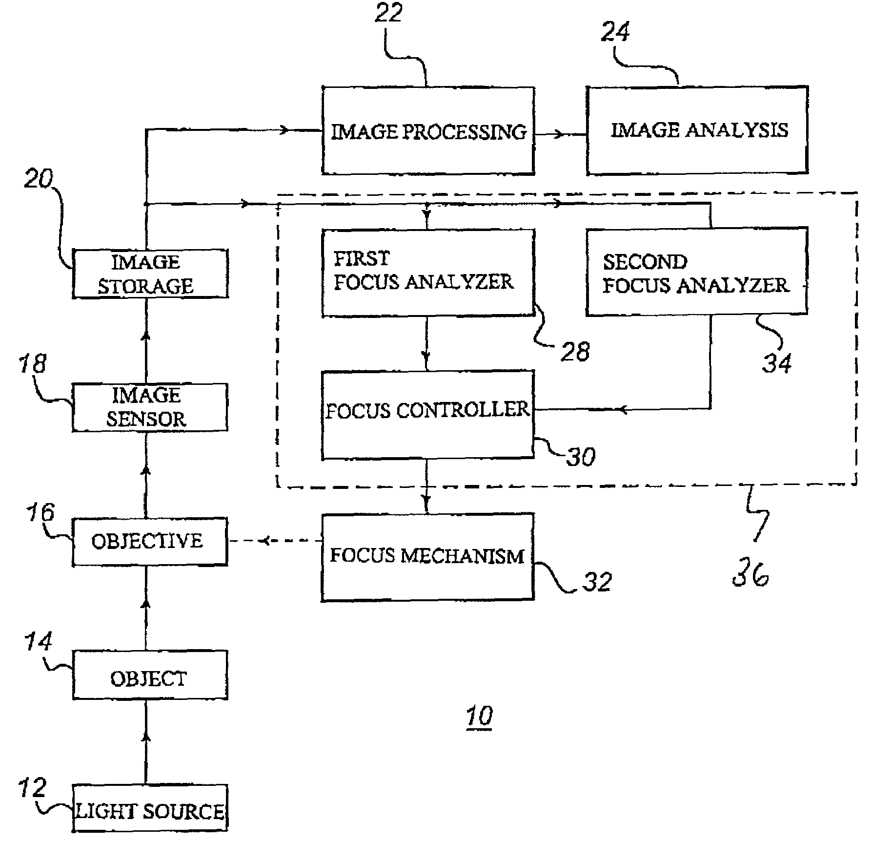
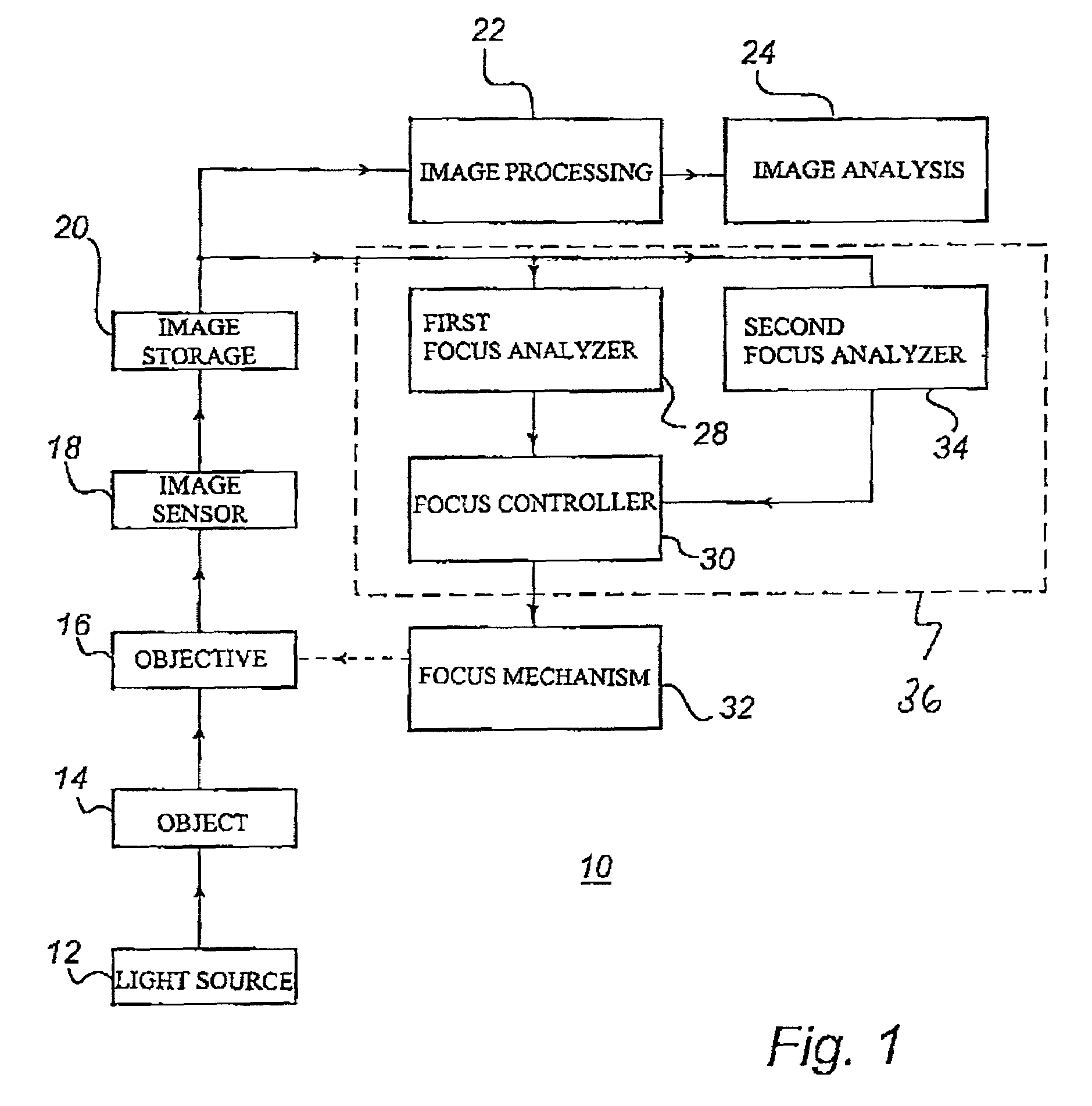
[0073]FIG. 1 is a schematic view of an optical system in the form of an automatically focusing microscope system 10. The microscope system 10 has a light source 12, which illuminates an object 14 which is to be studied in the microscope. The object 14 can be, for instance, a blood smear on a slide, in which one wants to study white blood cells, and in which red blood cells are used as a basis for automatic focusing.

[0074]The microscope system 10 further comprises an objective 16, which is adapted to reproduce by means of the light from the light source 12, that part of the object 14 which is within the field of view of the objective on a digital image sensor 18, which produces an image in electronic form. The image produced by the image sensor 18 is stored in an image storage 20. An image-processing unit 22 and an image-analyzing unit 24 are connected to the image storage 20. These units are intended for processing of the useful images from the image sensor 18. An example of process...


PUM


Abstract

A method and device for automatic focusing in an optical system is provided. A structure having a periphery is reproduced by an objective and an electronic representation of the structure reproduced by the objective is generated. The intensity variation at the periphery of the structure is analyzed in the electronic representation. An application focus value, indicating how the current focus position of the objective is related to an optimal focus position for an application, is determined using the intensity variation. The application focus value indicates whether the current focus position of the objective is above or below the optimal focus position and how far away the current focus position of the objective is from the optimal focus position.

Description

CROSS REFERENCE TO RELATED APPLICATION[0001]This application claims the benefit of U.S. Provisional Application No. 60 / 150,439, filed Aug. 24, 1999.FIELD OF THE INVENTION[0002]The present invention relates to a method in an optical system, comprising the steps of reproducing a structure having a periphery by means of an objective and producing an electronic representation of the structure reproduced by the objective. The invention also relates to devices for use in an optical system and a storage media, on which a computer program for use in an optical system is stored.BACKGROUND ART[0003]Microscopes and other optical systems need be focused on the object or the structure which the system reproduces. For a system which scans an object, continuous refocusing operations are necessary since the object is seldom planar. For instance, a height variation by some tenths of a micrometer of the object is sufficient for the object to get into the outer edge of the depth of focus of a high-res...

Claims


Application Information

Patent Timeline
Patent Type & Authority Patents(United States)
IPC IPC(8): H04N5/232H04N7/18
CPCH04N5/23212G02B21/244H04N23/67
Inventor ROSENQVIST, ANDERS
Owner CELLAVISION
Why Eureka
Try Eureka