X-ray generator and adjusting method of the same

a technology of x-ray generator and adjusting method, which is applied in the direction of x-ray tubes, cell components, nuclear engineering, etc., can solve the problems of increasing manufacturing costs, complicated changes in the work of the anticathode, and difficulty in making the anticathode an easily detachable structure, so as to reduce adjustment and solve differences in the emitting direction. , the effect of easy adjustmen

Active Publication Date: 2006-04-25
BRUKER JAPAN KK
View PDF6 Cites 1 Cited by
  • Summary
  • Abstract
  • Description
  • Claims
  • Application Information

AI Technical Summary

Benefits of technology

[0011]The present invention is provided in view of the above-described circumstances, and an object of the present invention is to provide an X-ray generator capable of easily solving differences in an emitting direction caused by switching of X-ray types, and capable of reducing adjustment as much as possible on the side of an optical system, and a method of adjusting the same.
[0023]According to the present invention, the optical element emitting the incident X-rays as the diffracted X-rays is arranged in the taking-out route of the X-ray emitted from the anticathode parts, and the angle of the optical element is made adjustable by the adjustment mechanism. Therefore, the emitting directions of the diffracted X-rays with respect to the incident X-rays emitted from each anticathode can be aligned to one direction, when the anticathode parts, against which the thermoelectrons from the cathode collide, are switched by moving the cathode. Accordingly, even when the types of the X-ray are switched, labor for adjusting the optical system on the side of the diffractometer can be minimize.
[0024]Specifically, for example, by providing Cu (copper) and Mo (molybdenum) as the anticathode parts, the device is made to be capable of using the Cu—Kα ray and the Mo—Kα ray by switching. In this case, twice the wavelength 0.71 Å of the Mo—Kα ray (1.42 Å) is closely related to the wavelength 1.54 Å of the Cu—Kα ray. Therefore, the angle of the optical element and the moving position of the cathode are determined so as to make the emitting direction of the n-th diffracted X-ray with respect to the Cu—Kα ray made incident to the optical element, and the emitting direction of the 2n-th diffracted X-ray with respect to the Mo—Kα ray, identical to each other. Then, the posture of the optical element is adjusted to the angle thus determined, and the position of the cathode is also adjusted. Thus, the emitting directions of the X-rays from the optical element can be aligned to one direction by simple adjustment.

Problems solved by technology

However, it is generally not easy to make the anticathode of the X-ray generator an easily detachable structure.
Especially, in the case of a rotary anticathode type X-ray generator to obtain large volume or high intensity X-rays, there are fundamental difficulties in making the anticathode itself an easily detachable structure, because a coolant must be circulated in the anticathode to cool the anticathode, the anticathode itself serves as a movable portion rotating at a high speed, the circumferences of the cathode and the anticathode are required to be a vacuum atmosphere, and so on.
Even when such difficulties are overcome, there are still problems that changing work of the anticathode is complicated, and a manufacturing cost is significantly increased.
Therefore, the problem is that the above-described situation must be corrected on the side of the optical system such as a goniometer, and much time is spent for adjusting the optical system.

Method used


Image

  • X-ray generator and adjusting method of the same
  • X-ray generator and adjusting method of the same
  • X-ray generator and adjusting method of the same

Examples


Embodiment Construction

)

[0028]Preferred embodiment of the present invention will be explained below referring to the drawings.

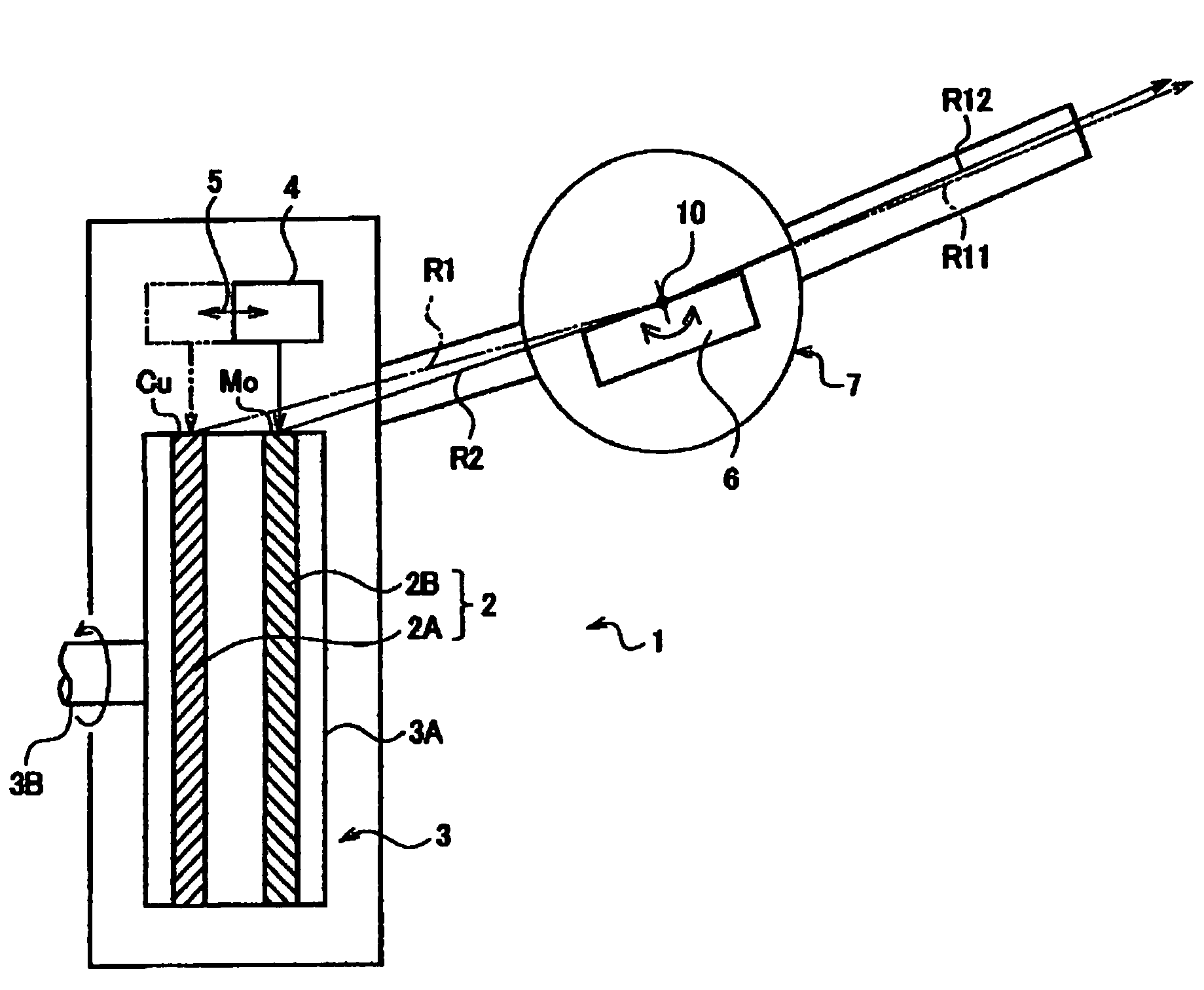
[0029]FIG. 1 is a schematic diagram of an X-ray generator 1 in the embodiment. The X-ray generator 1 comprises:

[0030]an anticathode unit 3 in which a plurality of anticathode parts 2 (2A and 2B) to emit X-rays by being collided with thermoelectrons are disposed side by side;

[0031]a cathode 4 to release the thermoelectrons towards one of the anticathode parts 2 on the anticathode unit 3;

[0032]a cathode moving mechanism 5 (shown by an arrow) to switch the anticathode parts 2, against which thermoelectrons from the cathode 4 collide, by moving the cathode 4 in an aligning direction of the anticathode parts 2 on the anticathode unit 3;

[0033]an optical element 6 disposed in a taking-out route of the X-rays emitted from the anticathode parts 2, to emit incident X-rays as diffracted X-rays.

[0034]The anticathode unit 3 is formed in a rotary anticathode type, provided with a plurality of an...


PUM

PropertyMeasurementUnit
angleaaaaaaaaaa
incident angleaaaaaaaaaa
structure analysisaaaaaaaaaa

Abstract

To solve a difference in an emitting directions by switching the types of X-rays. An X-ray generator comprises: an anticathode unit 3 in which a plurality of anticathode parts 2 (2A and 2B) that emit X-rays by collision of thermoelectrons are disposed side by side; a cathode 4 for releasing the thermoelectrons toward the anticathode parts 2A and 2B on the anticathode unit 3; and a cathode moving mechanism that switches the anticathode parts, against which the thermoelectrons from the cathode 4 collide by moving the cathode 4 along the diction of aligning anticathode parts 2A and 2B. In such an X-ray generator, an optical element 6 is arranged, which emits incident X-rays R1 and R2, in a taking-out route of the X-rays emitted from the anticathode parts 2, as diffracted X-rays R11 and R12, and also an adjustment mechanism 7 that aligns emitting directions of the diffracted X-rays with respect to the incident X-rays emitted from each anticathode part, to one direction, when the anticathode parts, against which the thermoelectrons from the cathode collide, are switched by moving the cathode.

Description

BACKGROUND OF THE INVENTION[0001]1. Field of the Invention[0002]The present invention relates to an X-ray generator and a method for adjusting the same.[0003]2. Description of the Related Art[0004]As an X-ray source at a laboratory level in single crystal structure analysis using X-rays, mainly Cu—Kα rays and Mo—Kα rays are used. The former is mainly used for the analysis of an organic compound and the latter is mainly used for the analysis of an inorganic compound Accordingly, in the case of, for instance, an X-ray diffractometer shared in the analysis of the organic compound and the analysis of the inorganic compound, an X-ray source of the X-ray generator needs to be changed, in accordance with samples of a user.[0005]In the case of an X-ray generator which radiates X-rays from a surface of an anticathode (target) by colliding thermoelectrons emitted from a cathode (filament) against the anticathode, the material of the anticathode to be collided with thermoelectrons needs to be ...

Claims


Application Information

Patent Timeline
Patent Type & Authority Patents(United States)
IPC IPC(8): H01J35/24G21K1/06G01N23/20G21K5/02G21K5/08H01J35/06H01J35/08H01J35/10H05G1/00H05G1/70
CPCG01N23/20H01J35/08H01J35/06H01J2235/064H01J35/064H01M4/12H01M4/42H01M6/06
Inventor KATAYAMA, CHUJI
Owner BRUKER JAPAN KK
Why Eureka
Try Eureka