Tunable optical filter

a tunable filter and optical filter technology, applied in the field of tunable optical filters, can solve the problems of limiting the tunability of the filter, unable to show how to construct an arbitrary tunable modulator, and the device shown by dingel et al. is bulky and relatively expensive to manufacture, and achieves reliable, compact, and inexpensive tunable spectral filtering.

Inactive Publication Date: 2006-04-25
II VI DELAWARE INC
View PDF33 Cites 68 Cited by
  • Summary
  • Abstract
  • Description
  • Claims
  • Application Information

AI Technical Summary

Benefits of technology

[0018]It is therefore an object of this invention to provide methods and a

Problems solved by technology

Patel uses a single voltage generator to apply a potential difference across both portions of the cavity, which disadvantageously limits the tunability of the filter.
The device shown by Dingel et al. is bulky and relatively expensive to manufacture.
Saunders, however, does not show how to construct an arbitrary tunable modulator.
The attenuator

Method used


Image

  • Tunable optical filter
  • Tunable optical filter
  • Tunable optical filter

Examples


Embodiment Construction

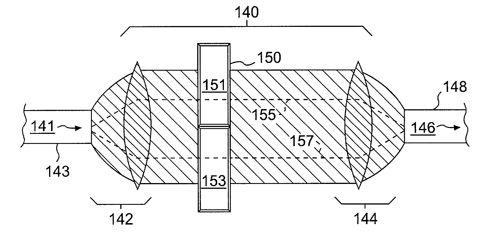
[0056]A filter consistent with this invention includes an optical assembly for receiving an incident optical signal, an optical assembly for providing a filtered optical signal, and a plurality of independently tunable filter elements. Each of the elements is located along a different optical path, although each of the paths intersects at least at the assemblies. Also, each of the filter elements filters a different component of the incident optical signal such that, when the components are combined, a filtered optical signal is formed.

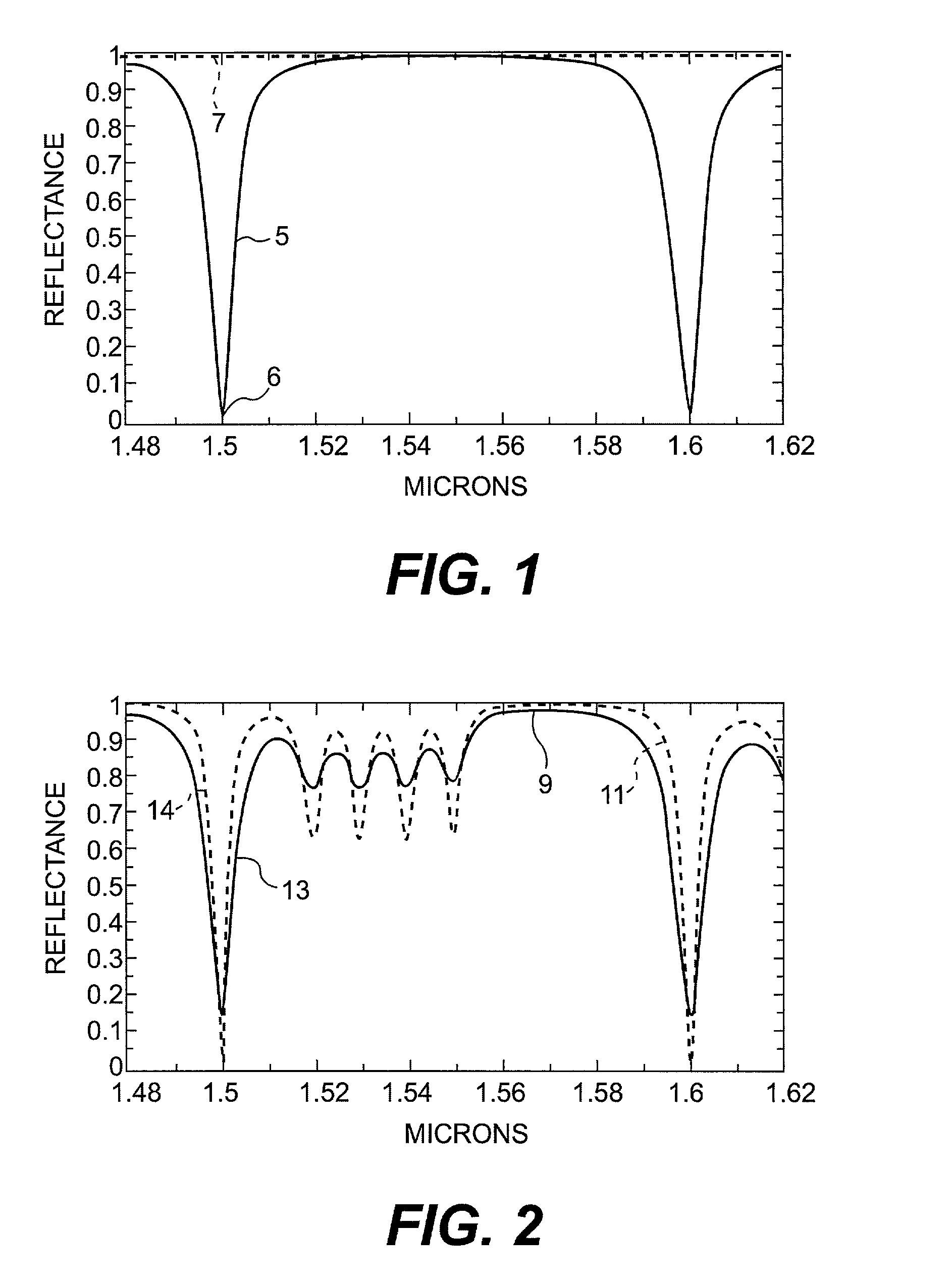
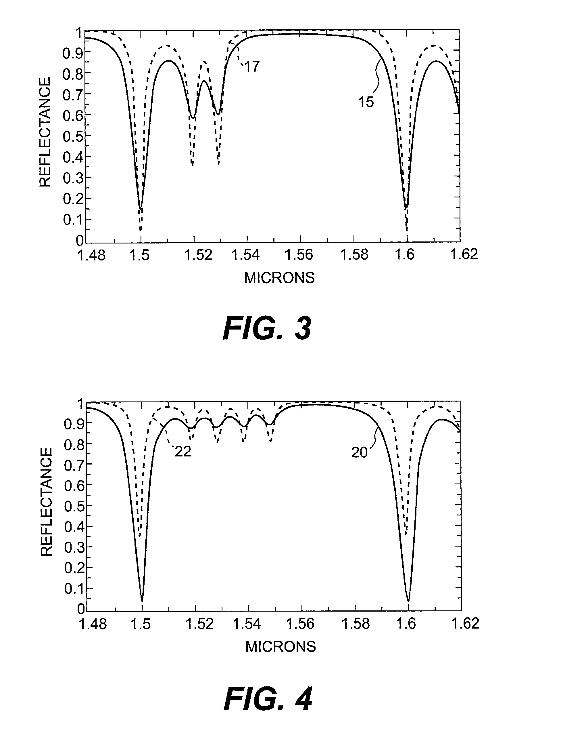
[0057]During operation, a beam is spatially divided into at least two different components that are separately directed to at least two of the filter elements (i.e., pixels). As used herein, a pixel is the smallest independently controllable element of a filter. Each of the pixels acts like a tunable filter that can be tuned to reject a particular band of frequencies. When the pixels simultaneously filter different components of the beam, a composite ...


PUM


Abstract

A tunable optical filter is provided that includes an array of independently tunable filter elements. Each of the elements is located along a different optical path that extends between an input and an output port. Optical assemblies for receiving an incident optical signal for providing a filtered optical signal are also provided. In one embodiment, polarization independent spectral filtering can be achieved. Wavelength selectable add/drop multiplexers and demultiplexers, dynamic gain equalizers and attenuators, optical channel blockers and branch filters, switches, and modulators are also provided. Furthermore, methods for constructing and operating filters consistent with this invention are also provided.

Description

FIELD OF THE INVENTION[0001]This invention relates to tunable optical filters, and more particularly to filters that have variable spectral reflectance and transmittance functions, and even more particularly to multi-wavelength optical communication systems and high-density wavelength-division multiplexed network systems.BACKGROUND[0002]It is known that tunable optical filters can be constructed from liquid crystals. For example, Patel U.S. Pat. No. 5,111,321 (hereinafter, “Patel”) shows a dual-polarization liquid crystal etalon filter that includes a nematic liquid crystal in a Fabry-Perot cavity. The crystal is divided into two portions that are buffed in orthogonal directions so that they align the liquid crystal parallel to their surfaces. Using a polarization beam diversity scheme, an input beam is split into its orthogonal polarization components and both portions of the Fabry-Perot cavity operate in equal amounts upon the components to induce a polarization independent filter...

Claims


Application Information

Patent Timeline
IPC IPC(8): G02F1/01G02F1/295G02F1/13G02B6/34G02B27/28G02F1/21G02F1/31
CPCG02B6/272G02B6/29358G02B6/29367G02B6/29383G02B6/29395G02F1/216G02B6/2937G02B6/2766G02F2203/12
Inventor SILBERBERG, YARONSUH, SEONGWOOCOHEN, GIL
Owner II VI DELAWARE INC
Why Eureka
Try Eureka