Rolling electronic length measuring device

a technology of electronic length measurement and measuring device, which is applied in the direction of measuring wheels, electric/magnetic measuring arrangements, instruments, etc., can solve the problems of difficult to accurately measure the length of a curved or non-planar surface with a metal tape measure, inconvenient use of cloth or fabric tape measures similar to those used by tailors in certain environments, and difficult to obtain certain measurements

Inactive Publication Date: 2006-05-02
IRWIN IND TOOL CO
View PDF23 Cites 17 Cited by
  • Summary
  • Abstract
  • Description
  • Claims
  • Application Information

AI Technical Summary

Benefits of technology

[0010]Alternatively, the axle may be directly coupled to the encoder disk without a gear train coupling the axle to the encoder disk. If a gear train is utilized, to prevent backlash when the directional movement of the device is quickly reversed, the axle or shaft supporting the second gear and encoder disk may be loosely supported in a bearing and biased towards the first gear using a spring.
[0011]In a refinement, the at least one wheel comprises two wheels coaxially connected together by the axle with the first gear disposed between the two wheels and mounted on the axle. By using two wheels, it is easier for the user to roll the measuring device along a straight line.
[0021]Also, each tapered point is preferably in vertical alignment with the outer surface of its respective side wall of the housing so that the tapered points can be accurately used to define the width of the housing which, in turn, can be easily accommodated for by the controller when making a measurement. Further, in a preferred embodiment, when an end stop is extended downward beyond the surface being measured (i.e. past the wheels), the inside surface of the end stop is in vertical alignment with the outer surface of its respective side wall of the housing so the inside surface of the end stop can be used as an accurate start or stop point of a measurement.
[0022]For example, the user can press a control button to indicate to the controller which side wall of the housing is serving as a starting point for the measurement. After the device has been rolled across the surface to be measured, the user then may press a button to indicate to the controller which side of the device serves as the end point for the measurement. If different side walls or sides of the device serve as the starting or end points, the controller can easily accommodate for the “width” of the upper housing of the device by adding the width of the housing to the computed length thereby providing for an accurate measurement.
[0024]In another refinement, the device includes a pair of guide rollers for stabilizing the device thereby providing a pair of measuring wheels and a pair of guide rollers.
[0027]In a refinement, the method may also accommodate for the width of the measuring device and the method may also include the option of dividing the measured length into equal segments and enabling the user to retrace the length and easily mark off the equal segments at predetermined “points.”

Problems solved by technology

One problem associated with conventional measuring devices such as tape measures, rulers, yard sticks or even sonic or laser type electronic devices is that certain measurements are difficult to obtain.
Specifically, accurately measuring the length of a curved or non-planar surface with a metal tape measure is difficult.
Further, cloth or fabric tape measures similar to the ones used by tailors are not convenient in certain environments, such as construction sites because they are not easily retracted to a coiled position like the common metal tape measures.
Electronic devices relying upon sonic or laser technology to measure distances are only suitable for straight measurements or line-of-site measurements.
Another problem associated with currently available length or distance measuring devices is that the manipulation of the obtained measurement must be performed by the user with or without the use of a separate calculator.
This process is cumbersome and tedious and often results in errors.
Errors in such measurements the fields in carpentry or home remodeling can be costly or damaging particularly if one or more holes are drilled in a wall or surface at one or more incorrect locations.
While traditional tape measures with a coiled measuring tape have been combined with calculators, these devices have not been commercially successful because they fail to address the problem of measuring the distance of a non-planar or irregular surface such as a curved wall.
Further, the known combination calculator / tape measure devices merely combine a calculator with a tape measure and do not provide the user with any convenient means for dividing a measured distance into equal lengths or segments and accurately marking those segments.

Method used


Image

  • Rolling electronic length measuring device
  • Rolling electronic length measuring device
  • Rolling electronic length measuring device

Examples


Embodiment Construction

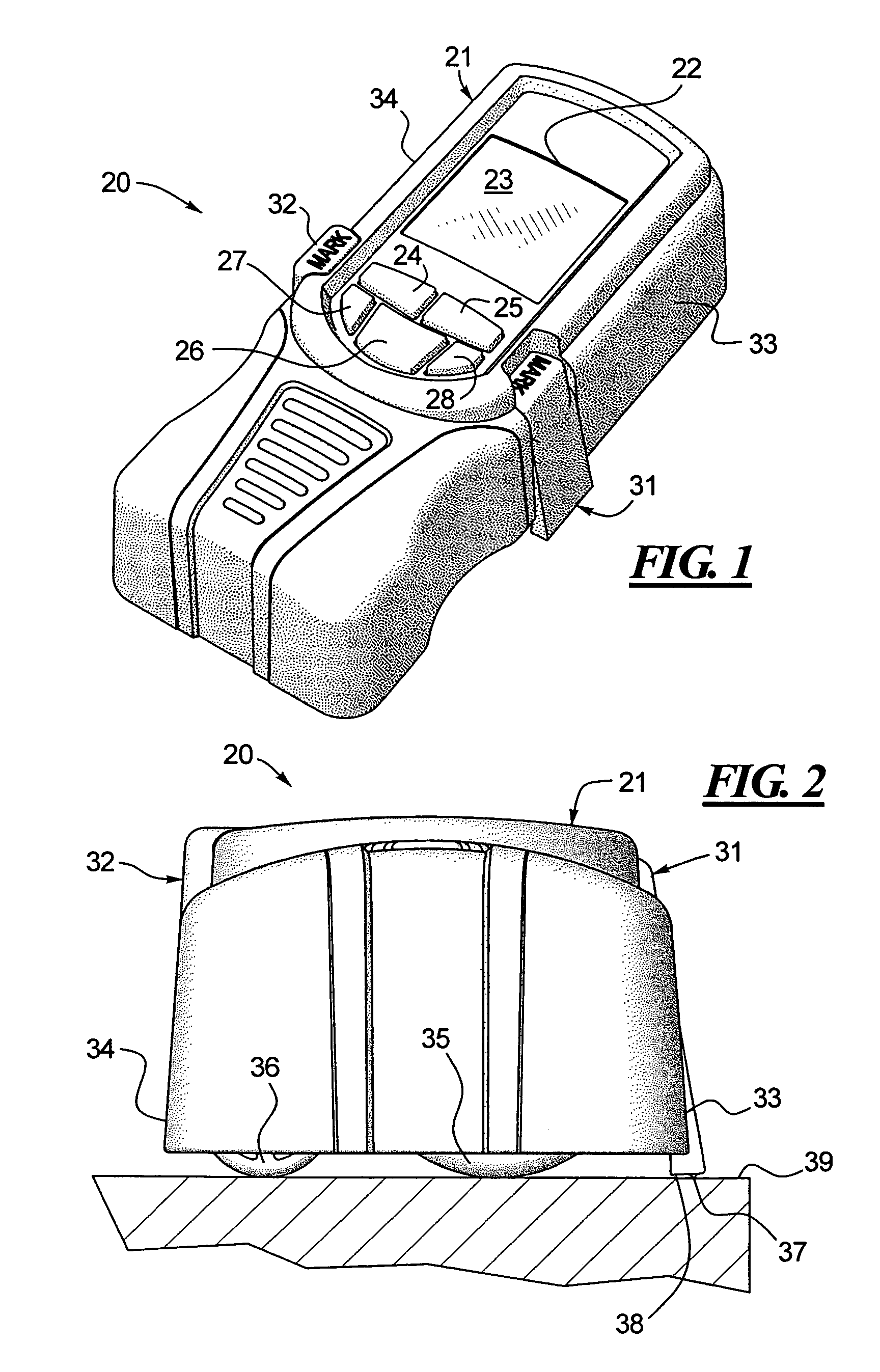
[0042]FIG. 1 illustrates a measuring device 20 that includes an upper housing 21 with an opening 22 for a display 23, preferably a LCD. The housing 21 also includes a plurality of openings providing the user with access to control buttons 24, 25, 26, 27 and 28. Further, the device 20 also includes end stops 31, 32 disposed in side walls 33, 34 respectively for providing convenient start and stop points for a measurement and for marking the surface being measured as described in greater detail below.

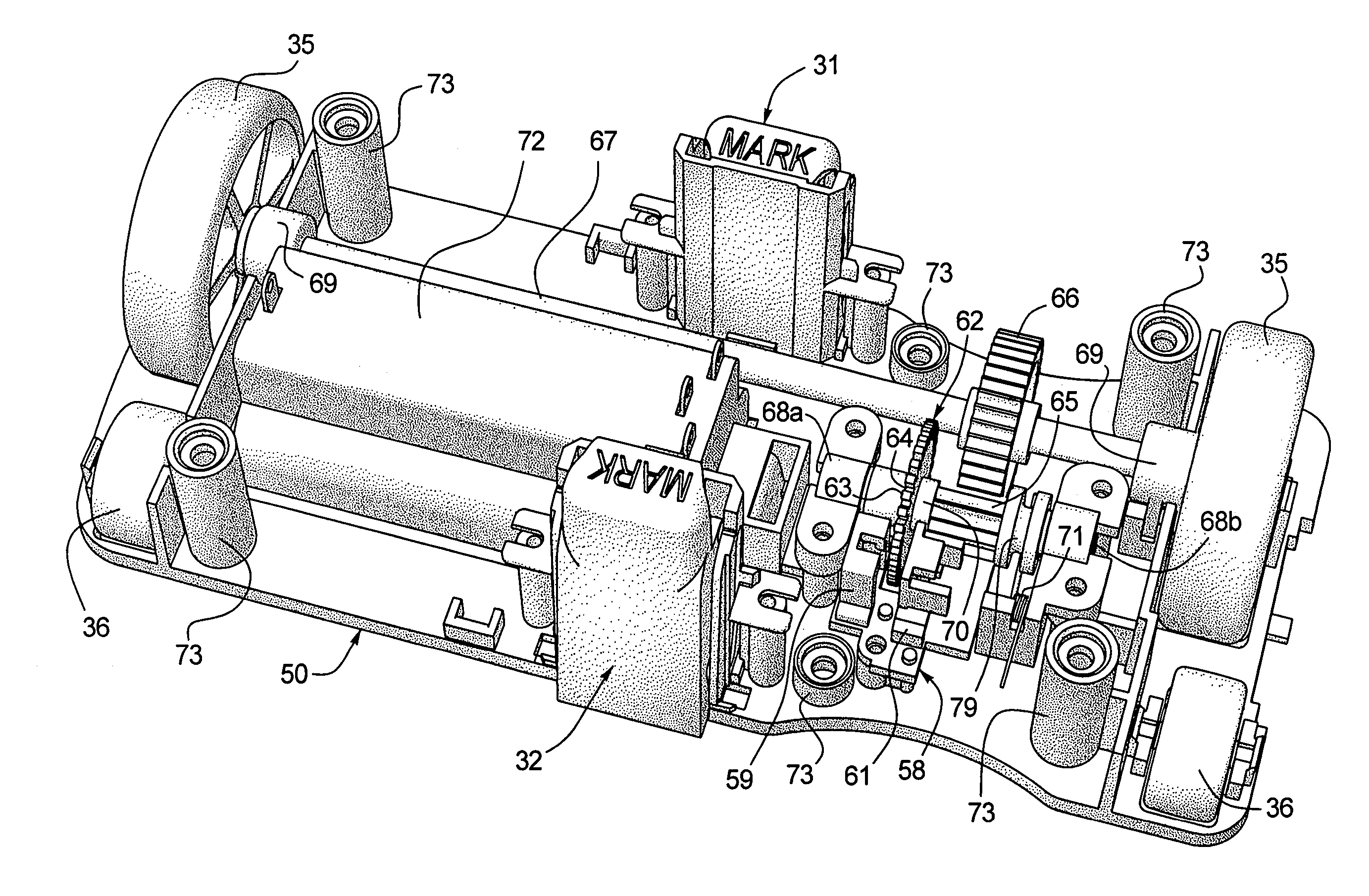
[0043]Turning to FIG. 2, the rolling device 20 includes a measuring wheel 35 (in this case a pair of measuring wheels 35 as shown in FIG. 7) that engages the surface to be measured. In a preferred embodiment, a pair of guide rollers shown at 36 is also provided. Preferably, two wheels 35 are utilized as the use of two wheels 35 makes it easier for the user to roll the device 20 in a straight line.

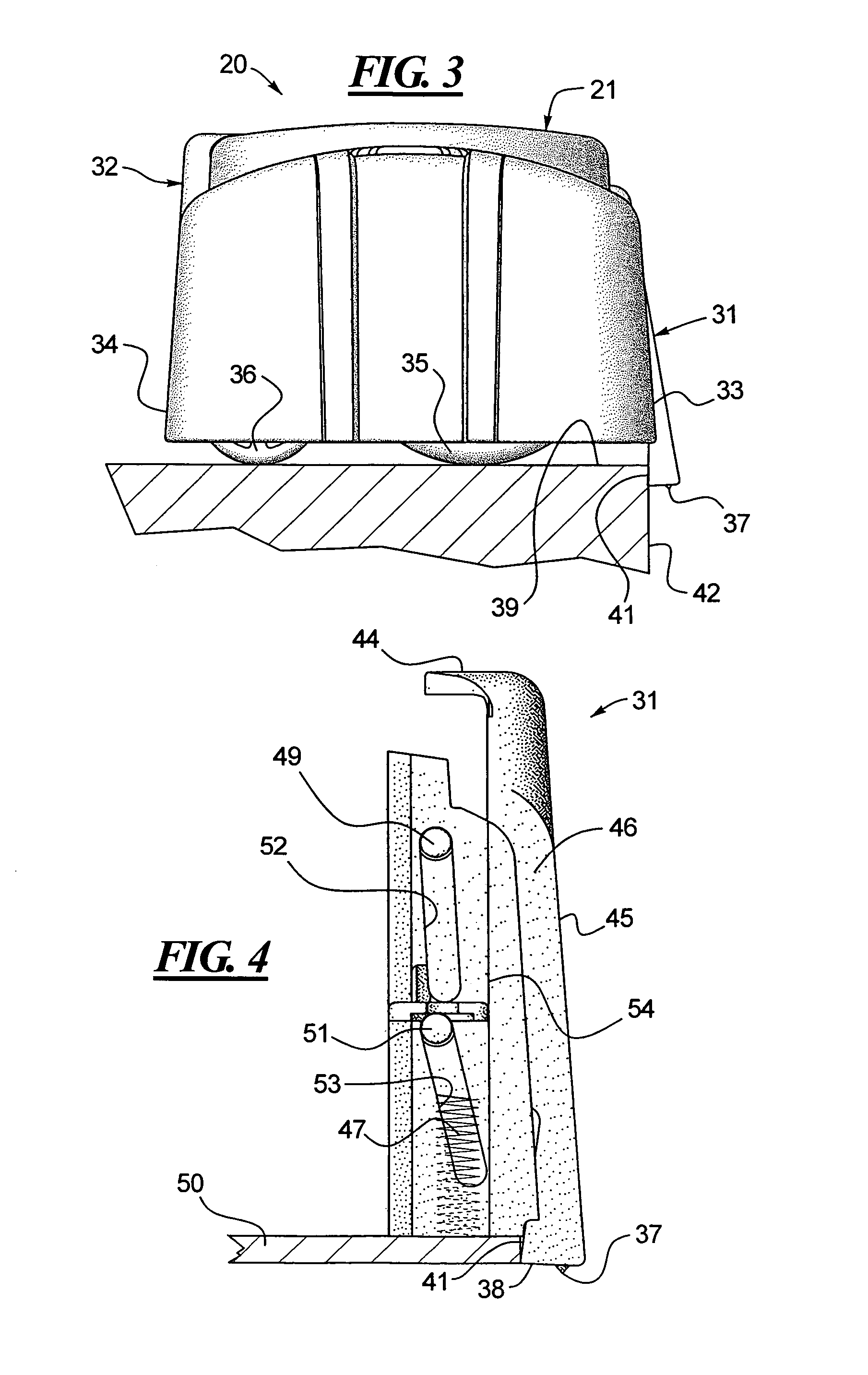
[0044]In FIG. 2, the end stop 31 has been pushed downward, overcoming the bias of a spring (S...


PUM


Abstract

An electronic measuring device is disclosed which includes a pair of wheels connected to an axle that passes through a drive gear. The drive gear is enmeshed to a second gear which, in turn, is coaxially connected to an encoder disk. The encoder disk has spaced-apart fins around its outer periphery. As the wheels turn and the encoder disk rotates, the fins and openings between the fins pass between an emitter and a receiver. The emitter and receiver are linked to a controller which calculates the distance traversed by the wheels based upon the number of fins that pass between the emitter and receiver, or with an active counting system (ACS). The controller also includes functions to establish start and stop points for a measurement and an easy means for dividing a measured distance into equal parts or segments and a means for marking the boundary points that define the segments when the measuring device is rolled back across the measured distance. The device can be used on both planar and non-planar surfaces.

Description

TECHNICAL FIELD[0001]This disclosure relates generally to measuring devices, such as measuring tapes. However, the disclosed device is an electronic measuring device that rolls along the surface to be measured. Accordingly, the device is suitable for non-planar surfaces including curved surfaces. The disclosed device provides an alternative to metallic coiled tape measuring devices, cloth or plastic measuring tapes and sonic or laser measuring devices.BACKGROUND OF THE RELATED ART[0002]One problem associated with conventional measuring devices such as tape measures, rulers, yard sticks or even sonic or laser type electronic devices is that certain measurements are difficult to obtain. Specifically, accurately measuring the length of a curved or non-planar surface with a metal tape measure is difficult. Further, cloth or fabric tape measures similar to the ones used by tailors are not convenient in certain environments, such as construction sites because they are not easily retracted...

Claims


Application Information

Patent Timeline
Patent Type & Authority Patents(United States)
IPC IPC(8): G01B3/12
CPCG01B3/12
Inventor WILLIAMS, MICHAELSPANSKI, JEFFREY L.NASH, DEREK J.SMITH, JOHN C.GIST, DAILY
Owner IRWIN IND TOOL CO
Why Eureka
Try Eureka