
Method and system for casting metal and metal alloys

a technology of metal alloys and methods, applied in the field of methods and systems for casting metal and metal alloys, can solve the problems of not cost-effective when prior art casting methods are used, and achieve the effect of cost-effectiveness

Inactive Publication Date: 2006-05-02
OUTOKUMPU OY
View PDF7 Cites 5 Cited by
  • Summary
  • Abstract
  • Description
  • Claims
  • Application Information

AI Technical Summary

Benefits of technology

The invention introduces a new method and system for casting metals and metal alloys. It involves using a casting crucible that is divided into two areas with a separating wall. The crucible is placed in a melting / holding furnace and has weep holes for the base metal melt to enter the first area. The alloying is done dynamically in the first area and the casting from the second area of the crucible. The alloyed metal flows to the casting area through a gap between the bottom of the crucible and the separating wall. This method and system allows for quick and flexible casting of low volumes of various copper alloys, which is not cost-effective with prior art methods. The invention solves the drawbacks of prior art methods and systems and provides an advantageous solution for casting metals and metal alloys.

Problems solved by technology

By placing a separate casting crucible to the melting / holding furnace it is possible to have a quick change flexible casting system for casting low volumes of a variety of copper alloys that is not cost-effective when prior art casting methods are used.

Method used


Image

  • Method and system for casting metal and metal alloys
  • Method and system for casting metal and metal alloys

Examples


Embodiment Construction

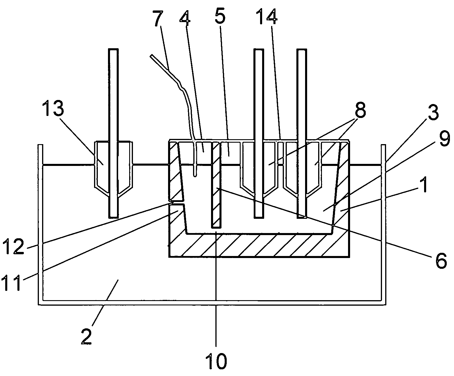
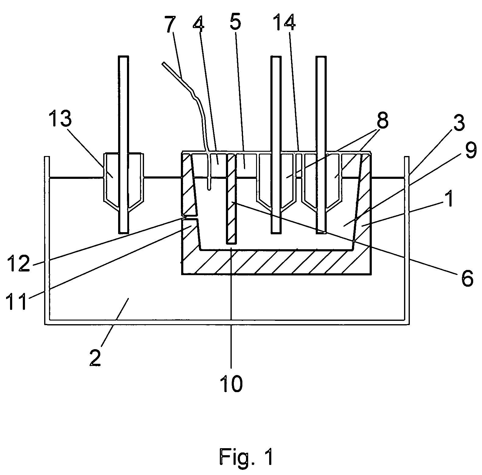
[0011]In FIG. 1 the casting crucible 1 is placed in a base metal melt 2 in a melting / holding furnace 3. The base metal melt 2 in the holding furnace 3 could for example be copper, copper alloy or some other metal. The casting crucible 1 is divided into to two areas 4 and 5 by a separating wall 6. The first area 4 is alloying area, where the master alloy or alloys 7 are brought to the base metal melt 2. The second area 5 is the casting area, where the casting of the product is done. In the second area 5 there are two casting dies 8, immersed deep into the alloyed metal melt 9 and the solidified melt is then pulled upwards while being further cooled. The number of casting dies 8 is freely selectable. Through the gap 10 between the separating wall 6 and the wall 11 of the casting crucible 1 the alloyed metal melt 9 can flow from the first / alloying area 4 to the second / casting area 5.

[0012]The base metal melt 2 in the holding furnace 3 is surrounding at least partly the casting crucible...


PUM

PropertyMeasurementUnit
volumeaaaaaaaaaa
volumesaaaaaaaaaa
affinityaaaaaaaaaa

Abstract

The invention is relating to a system for casting metal, the system comprising a holding furnace (3) containing a base metal melt (2), at least one casting crucible (1) mounted inside the holding furnace (3) and situated at least partly in the base metal melt (2), the said casting crucible (1) divided to at least first volume (4) and second volume (5) with a separating wall (6), which separating wall (6) is forming a gap (10) with the casting crucible wall (11) said casting crucible (1) having at least one opening (12) in the wall (11) from the first volume (4) to the base metal melt (2) in holding furnace (3) and having means to import alloying material (7) to the first volume (4) and having at least one casting die (8) in the second volume (5) inserted into the alloyed metal melt (9). The invention also relates to a method of casting metal.

Description

FIELD OF THE INVENTION[0001]This invention relates to method and system for casting metal and metal alloys.BACKGROUND OF THE INVENTION[0002]Casting of metal and metal alloys is typically completed by melting metal cathode or scrap and then alloying the metal to desired chemistry. The primary method for producing metal alloys is to melt the base metal in a melt furnace and then either alloy the metal in the melt furnace or transfer the metal to a holding / casting furnace and alloy the metal at that point.[0003]Continuous casting of metals can be done either through the bottom of the melt container, through the wall of the melt container (horizontal casting) or using upward casting process. Documents relating to the upward casting process are for example U.S. Pat. No. 2,553,921 and WO 02 / 20194 A1.[0004]In upward casting process the profiled metal products are continuously cast by maintaining a water-cooled metal nozzle immersed into a melt to receive and cool the melt. The nozzle is im...

Claims


Application Information

Patent Timeline
Patent Type & Authority Patents(United States)
IPC IPC(8): B22D11/04
CPCB22D11/145B22D11/108
Inventor NIPPERT, RUSSELLSWANK, BRIANHIEKKANEN, ILPPOKOPPINEN, ILPO
Owner OUTOKUMPU OY
Learn More