Heat dissipating module

a heat dissipating module and heat dissipation module technology, applied in the direction of insulated conductors, semiconductor/solid-state device details, cables, etc., can solve the problems of low yield ratio, high cost, complex whole assembly work, etc., and achieve high yield ratio, easy assembly, and high heat dissipation efficiency

Active Publication Date: 2006-05-02
HUANG TSUNG HSIEN
View PDF14 Cites 28 Cited by
  • Summary
  • Abstract
  • Description
  • Claims
  • Application Information

AI Technical Summary

Benefits of technology

[0006]It is an objective of the present invention to provide a heat dissipating module, which, when compared with the prior art module, can be more easily assembled at a higher yield ratio and can result in a higher heat dissipating efficiency. To achieve this objective, the present invention provides a heat dissipating module comprising a plurality of fins having same or different shapes, a plurality of heat dissipating tubes, and a seat made of solid metal. The plurality of fins are stacked one next to another; each fin has a plurality of upper penetrating holes; the upper penetrating holes of the fins are aligned to form a plurality of through holes; and a lower side of each fin has a plurality of trenches. The plurality of heat dissipating tubes are sealed at both ends with working liquid filled in the tubes. One end surface of the seat is formed with a plurality of slots corresponding to the trenches of the fins; two upper sides of each slot are extended with two shaping sheets, which can be pressed and bent to form a round hole with the slot. The lower legs of the plurality of heat dissipating tubes can be embedded in the slots of the seat and then the two shaping sheets are pressed and bent to tightly fold around the lower legs of the heat dissipating tubes. The lower legs of the heat dissipating tube pass through the upper penetrating holes and the upper legs of the heat dissipating tube pass through the trenches so that the fins are tightly pressed to the seat. Thereby heat can be transferred through the seat, the heat dissipating tubes and the fins to be dissipated. Thus a heat dissipating module is formed.

Problems solved by technology

Therefore, the whole assembly work is complex and the cost high, while the yield ratio is low.

Method used


Image

  • Heat dissipating module
  • Heat dissipating module
  • Heat dissipating module

Examples


Embodiment Construction

[0022]In order that those skilled in the art can further understand the present invention, a detailed description of the preferred embodiments will be provided in the following. The description and the appended drawings is provided only to enable those skilled in the art to understand the objects, features, and characteristics of the present invention, but not to be used to confine the scope and spirit of the present invention defined in the appended claims.

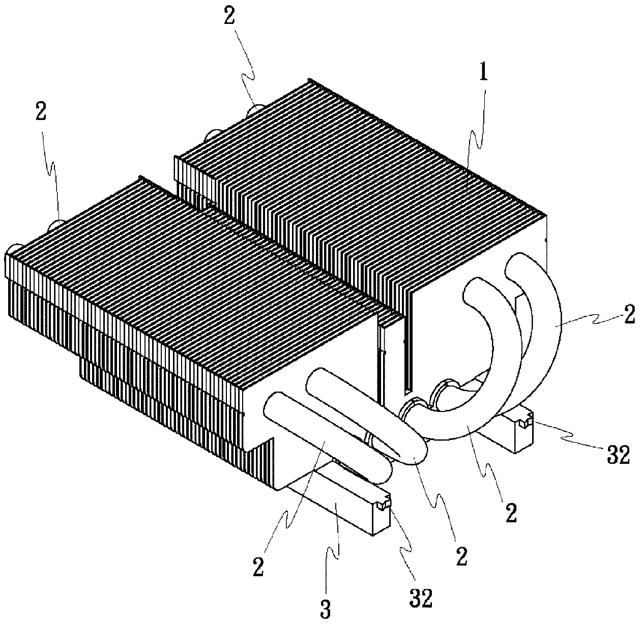
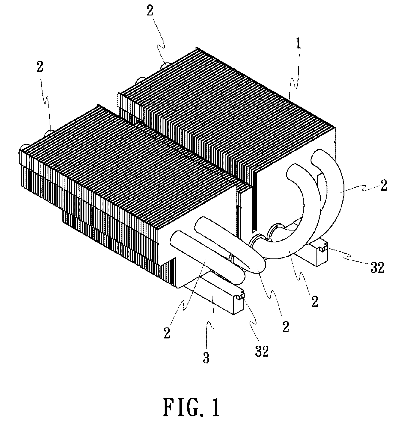
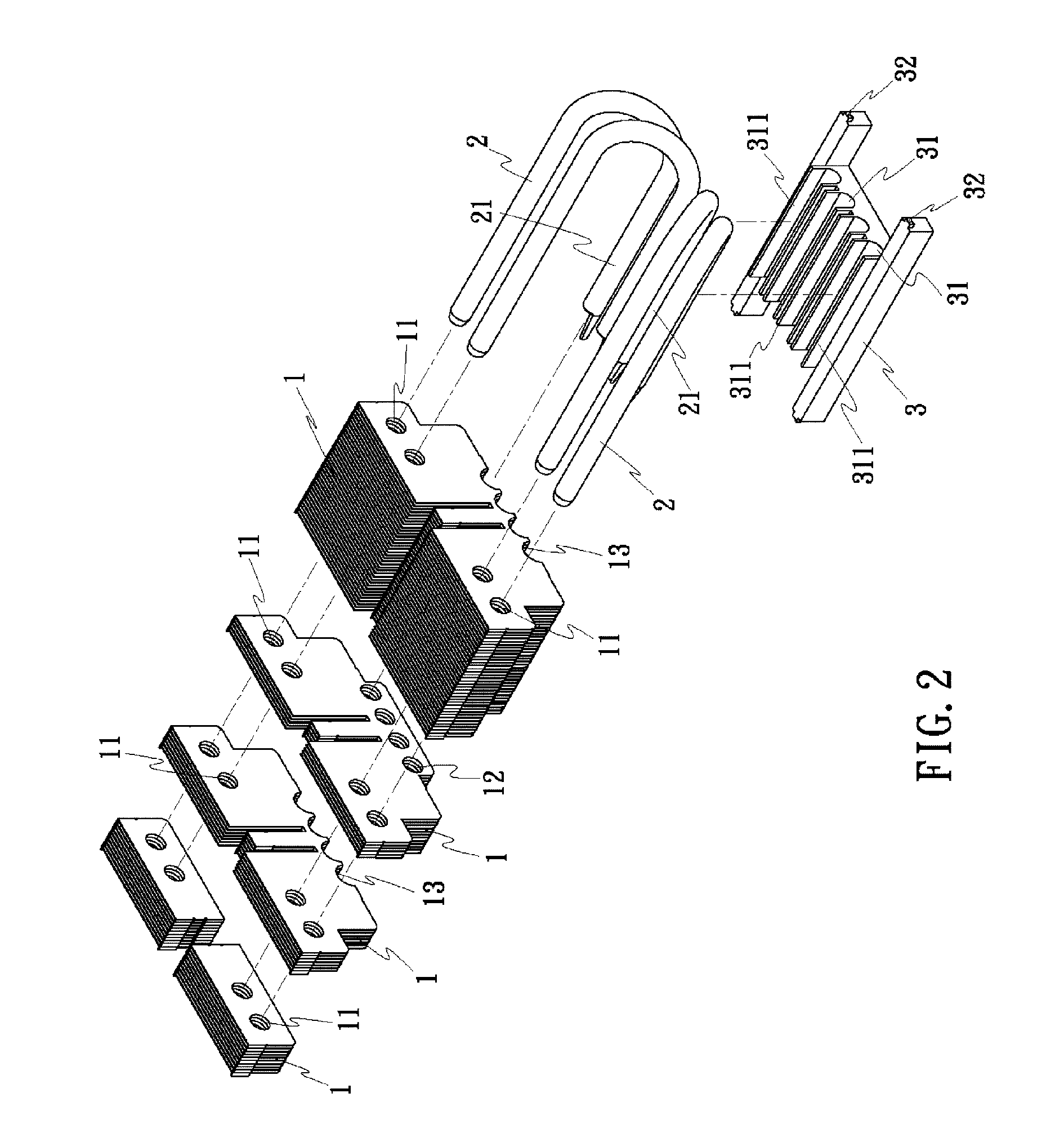
[0023]Referring to FIGS. 1 and 2, the heat dissipating module of the present invention has the following elements: a plurality of fins 1 having same or different shapes; a plurality of heat dissipating tubes 2; and a seat 3 made of solid metal (such as copper).

[0024]The fins 1 are stacked one next to another. Each fin 1 has a plurality of upper penetrating holes 11. The upper penetrating holes 11 of the fins 1 are aligned to form a plurality of through holes across the fins. Each of the fin 1 (except those in a last section) has ...


PUM


Abstract

A heat dissipating module is disclosed, which comprises a plurality of fins having same or different shapes, a plurality of heat dissipating tubes, and a seat. The fins are stacked one next to another, each fin having a plurality of upper penetrating holes and a plurality of lower grooves or holes. The seat is formed of solid metal with a plurality of slots, each slot corresponding to the lower groove of the fin and having two upper sides extended with two shaping sheets. When the two shaping sheets are pressed and bent, they form a round hole with the slot for receiving a heat dissipating tube. This invention will result in improved heat dissipation.

Description

BACKGROUND OF THE INVENTION[0001](a) Field of the Invention[0002]The present invention relates to a heat dissipating module having heat dissipating tubes and a seat. More particularly, it relates to such a heat dissipating module without using tin glue or other welding agents for combining the heat dissipating tubes and the seat. Thus higher heat dissipating efficiency between the heat dissipating tubes and the seat can be achieved.[0003](b) Description of the Prior Art[0004]Referring to FIG. 13, a conventional heat dissipating module includes a plurality of fins (made of a metal such as aluminum or copper), a plurality of heat dissipating tubes 20 (both ends of which are sealed with working liquid contained therein) and a seat 30 (made of a metal such as copper, thus also called a copper seat). The heat dissipating fins are stacked one next to another. The heat dissipating tubes pass through the fins and the heat dissipating tubes are welded to the seat by tin glue or other selecte...

Claims


Application Information

Patent Timeline
Patent Type & Authority Patents(United States)
IPC IPC(8): F28D15/00
CPCF28D15/0266F28F1/32H01L23/427H01L2924/0002H01L2924/00F28D15/0275
Inventor HUANG, TSUNG-HSIEN
Owner HUANG TSUNG HSIEN
Why Eureka
Try Eureka