
Heat sink

a technology of heat sinks and heat sinks, which is applied in the direction of lighting and heating apparatus, instruments, laminated elements, etc., can solve the problems of less efficacy when used with modular electronic devices, the performance of the device may be substantially degraded, etc., and achieves the effects of low friction coefficient, and increasing the diffusion of hea

Inactive Publication Date: 2006-05-02
AVAGO TECHNOLOGIED FIBER IP SINGAPORE PTE LTD
View PDF13 Cites 18 Cited by
  • Summary
  • Abstract
  • Description
  • Claims
  • Application Information

AI Technical Summary

Benefits of technology

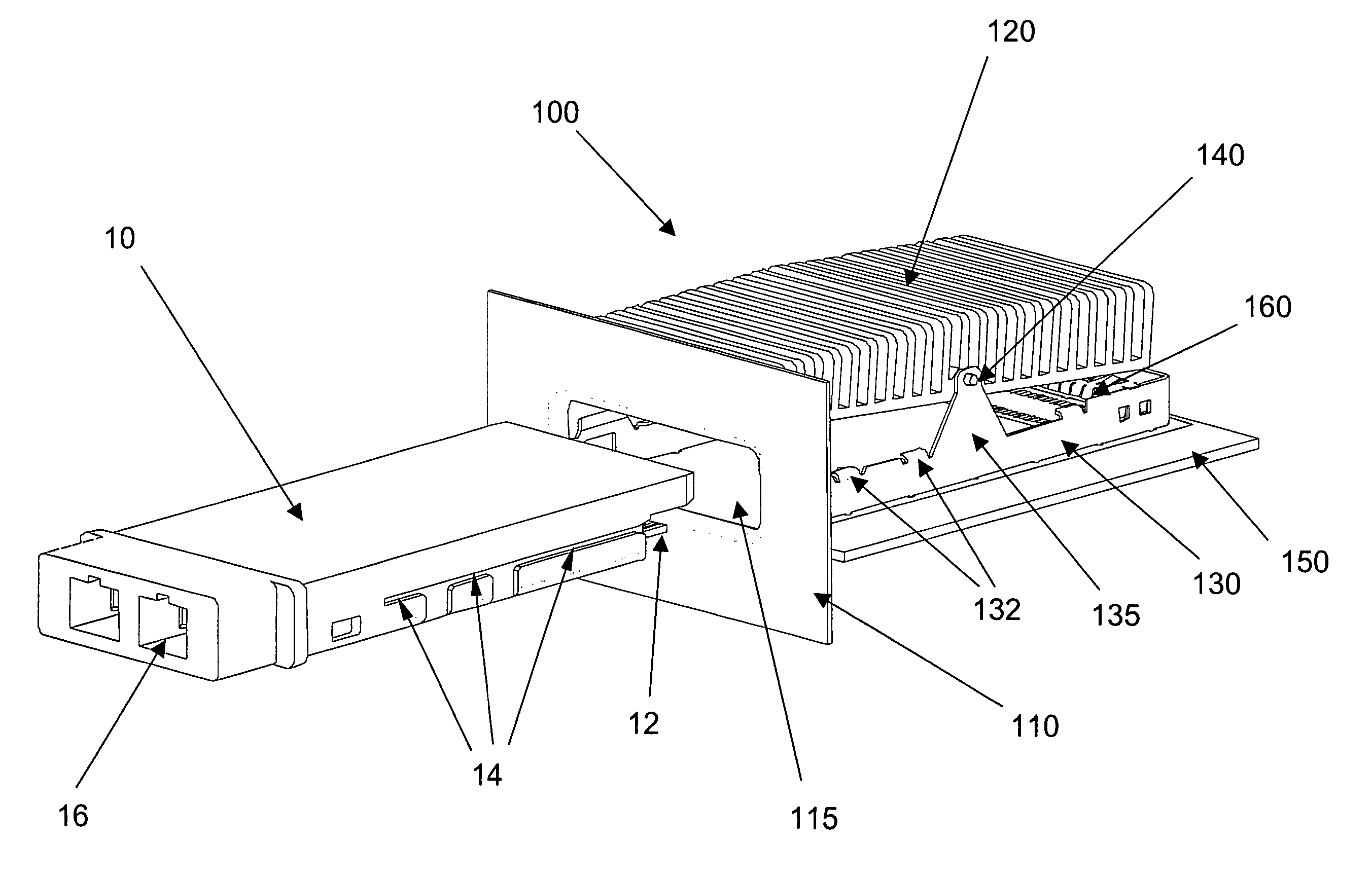
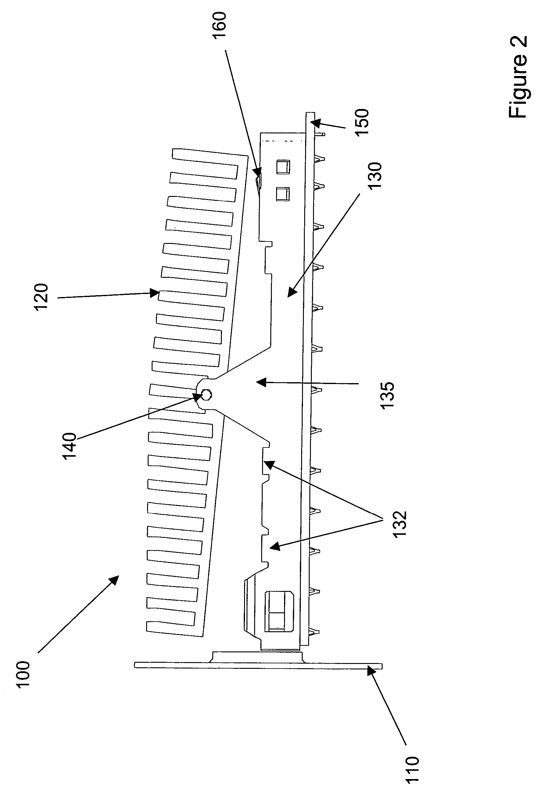
[0007]The heat sink arrangement may further comprise an aperture for receiving the equipment module and the pivotable heat sink may be inclined such that the surface of the pivotable heat sink that makes contact with the equipment module is presented towards the aperture. One or more of the faces of the heat sink may comprise one or more protrusions and the support for the pivotable heat sink may comprise a heat pipe. The pivotable heat sink may further comprise gas- or liquid-cooling apparatus. The surface of the pivotable heat sink that makes contact with the equipment module may comprise a material that increases the diffusion of heat from the equipment module.
[0008]According to a second aspect of the present invention there is provided an equipment module for use with a heat sink arrangement according to any preceding claim, the equipment module having a substantially cuboidal form and comprising guide means for engaging with the alignment means of the heat sink arrangement. The surface of the equipment module that makes contact with the pivotable heat sink may comprise a material that increases the diffusion of heat from the equipment module and / or a material having a low coefficient of friction. The surface of the equipment module that makes contact with the pivotable heat sink may comprise an inclined region.

Problems solved by technology

As the electronic and / or opto-electronic devices are typically stored within enclosures the heat generated by their operation can lead to significant problems as some devices may be destroyed if their core temperature is too great, or the performance of the device may be substantially degraded.
It has been observed that these techniques, while generally being sufficient to control the generation of heat and to mitigate any effects caused by increased temperature, are less efficacious when used with modular electronic devices.
As the module is slid into and out of the bay it is problematic to maintain an efficient thermal connection between the module and a heat sink, or other cooling equipment, that is provided inside the equipment rack so as to be in contact with an inserted module.

Method used


Image

  • Heat sink
  • Heat sink
  • Heat sink

Examples


Embodiment Construction

)

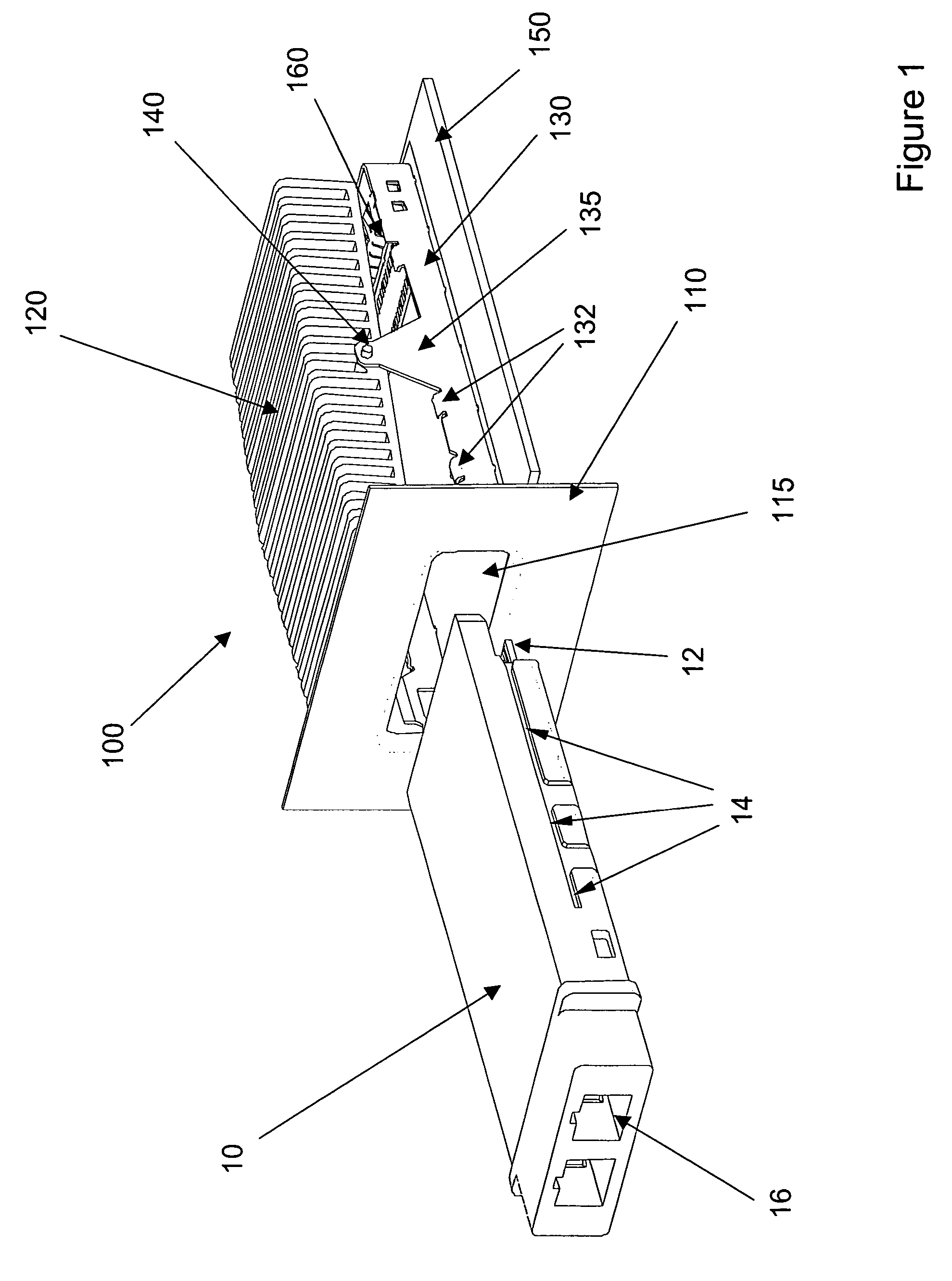
[0014]FIGS. 1 to 4 shows a schematic depiction of a heat sink arrangement 100 according to the present invention and an equipment module 10 that may be inserted into and removed from the heat sink arrangement 100. The equipment module 10 comprises internal communications interface 12, guide portions 14 and external communications interface 16. The internal communications interface is designed so as to be received within a corresponding interface within the heat sink arrangement 100 (see below) that is in communication with a transmission line or further piece of equipment. The external communications interface 16 is located on the front face of the equipment module that is not received within the heat sink arrangement for onward communication with a transmission line or a further piece of equipment. The guide portions 14 are preferably located on both side faces of the equipment module and are designed to engage with complementary features provided with the heat sink arrangement (s...


PUM

PropertyMeasurementUnit
coefficient of frictionaaaaaaaaaa
density ofaaaaaaaaaa
temperatureaaaaaaaaaa

Abstract

A heat sink arrangement for modular electronic and / or opto-electronic equipment is provided. The equipment module is inserted into an interface and a heat sink is pivotably arranged so as to be brought into contact with the inserted module. The equipment module may have an angled, or partially angled, so as to assist in bringing the module in contact with the heat sink.

Description

BACKGROUND OF THE INVENTION[0001]1. Field of the Invention[0002]This invention relates to heat sinks for use with electronic devices and in particular for use with modular electronic devices that are received within a rack or a bay.[0003]2. Brief Description of Related Developments[0004]As the density of transistors in electronic devices and the power output levels and switching speeds of opto-electronic devices increase, there is a corresponding increase in the heat generated by such devices. As the electronic and / or opto-electronic devices are typically stored within enclosures the heat generated by their operation can lead to significant problems as some devices may be destroyed if their core temperature is too great, or the performance of the device may be substantially degraded. Known techniques used to control the temperature of individual devices include the use of heat sinks, heat pipes and fans, and fans are also used to draw cool air into the enclosure holding the electron...

Claims


Application Information

Patent Timeline
Patent Type & Authority Patents(United States)
IPC IPC(8): F28F7/00G06F1/20F28D15/02F28F3/06
CPCF28D15/0233F28F3/06F28F2280/02F28D2021/0029H05K7/2029
Inventor THOMPSON, ANDREW LEELEESON, KIM
Owner AVAGO TECHNOLOGIED FIBER IP SINGAPORE PTE LTD
Learn More