Laser machining robot

a laser machining robot and laser machining head technology, applied in the direction of programmed manipulators, manufacturing tools, electric programme control, etc., can solve the problems of inability to accurately control the locus of the tip end point of the laser machining head, disadvantageous time-consuming operation for specifying conditions, and automatic suppression of the possibility of generating vibrations. , the effect of suppressing the possibility of generating vibrations

Inactive Publication Date: 2006-05-02
FANUC LTD
View PDF9 Cites 10 Cited by
  • Summary
  • Abstract
  • Description
  • Claims
  • Application Information

AI Technical Summary

Benefits of technology

[0008]Namely, by thus controlling, when the robot passes through a part (e.g., a corner) in which the acceleration or deceleration of the laser machining robot tends to be increased, the acceleration and the jerk are automatically suppressed, whereby a probability of generating a vibration is automatically suppressed. Further, by controlling laser machining conditions such as laser output in accordance with a change (normally a decrease) in velocity of a tip endpoint of the laser head (moving velocity of the laser machining robot) following the automatic suppression, stable laser machining with little influence of the aforesaid restriction can be realized. It is noted that limits (the maximum acceleration and the maximum jerk) of the acceleration and the jerk may be set in a design phase so as to be able to suppress the vibration at a required level.
[0009]The laser machining robot according to the present invention can be moved while automatically avoiding the generation of a vibration during machining and can easily realize a stable machining state. Therefore, the present invention can improve reliability and efficiency of laser machining carried out by the laser machining robot.

Problems solved by technology

However, even if this method is adopted, the following disadvantages often occur.
In three-dimensional machining, a vibration is generated following a rapid acceleration or deceleration of the robot and a locus of a tip end point of the laser machining head cannot be accurately controlled.
It disadvantageously takes lots of time to perform an operation for specifying the condition.

Method used


Image

  • Laser machining robot
  • Laser machining robot
  • Laser machining robot

Examples


first embodiment

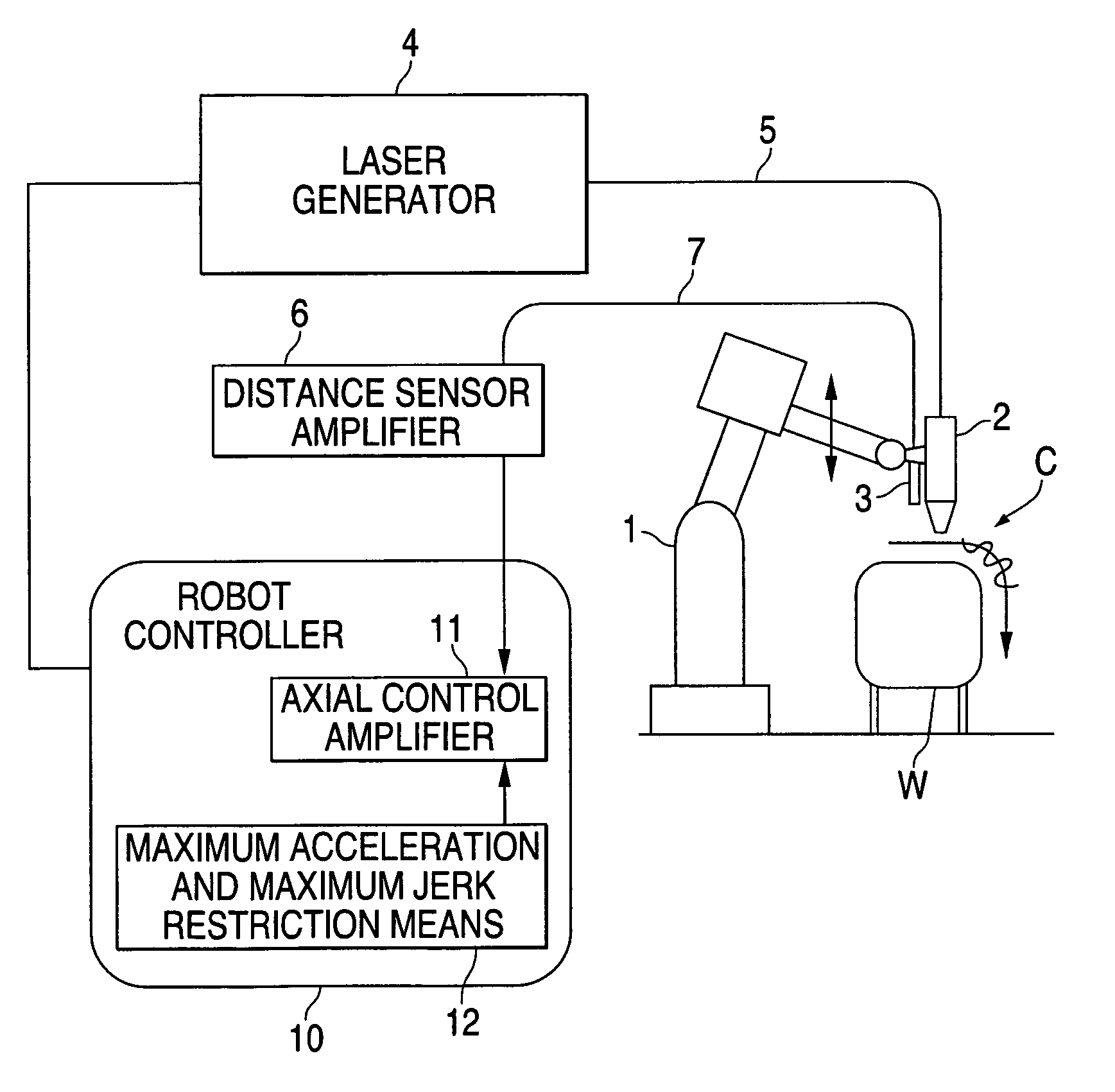
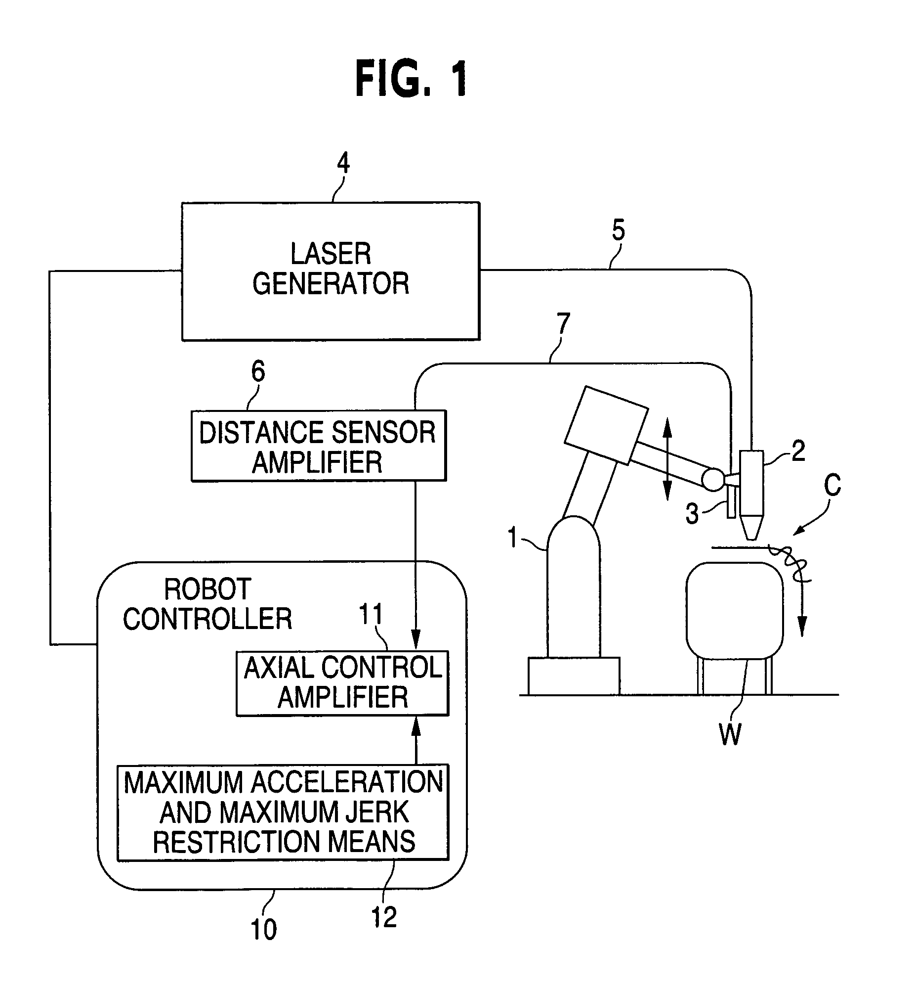
[0016]FIG. 1 shows a schematic diagram of the configuration of a machining system using a laser machining robot according to the present invention. The system shown in FIG. 1 includes a robot controller 10 connected to a laser machining robot (hereinafter, “robot”) 1 and controlling an operation of the robot 1, a laser machining head 2 attached to a tip end of an arm of the robot 1, and a laser generator 4 that transmits a laser beam for machining to the laser machining head 2 through an optical fiber 5. Laser output ON / OFF control and power control over the laser generator 4 are exerted by the robot controller 10 connected to the laser generator 4.

[0017]A distance sensor (or height sensor) 3 is attached to the tip end of the arm of the robot 1 in proximity to the laser machining head 2. This distance sensor 3 is connected to the robot controller 10 through a distance sensor amplifier 6 by a cable 7. The robot controller 10 controls a distance sensing operation of the distance senso...

second embodiment

[0047]FIG. 4A is a schematic diagram of the configuration of a machining system using a laser machining robot according to the present invention. In this system, an additional axis 8 is provided at the robot 1, and the distance sensor (or height sensor) 3 is attached to the laser machining head 2 itself. This additional axis is controlled in response to the height sensor signal from the distance sensor 3.

third embodiment

[0048]FIG. 4B is a schematic diagram of the configuration of a machining system using a laser machining robot according to the present invention. In this system, the distance sensor (or height sensor) 3 is attached to the laser machining head 2 itself, and the tracer control is carried out by controlling six axes of the robot 1.

[0049]Each of the system shown in FIG. 4A and the system shown in FIG. 4B executes the restriction on the acceleration and the jerk of the robot 1 as described in the first embodiment.

[0050]According to the present invention, the disruption of the locus caused by the vibration generated when the robot is quickly accelerated can be prevented. Accordingly, stable laser machining can be executed even in instances in which the corner is included in the machining route, e.g., for a complicated three-dimensional workpiece.


PUM

PropertyMeasurementUnit
accelerationaaaaaaaaaa
moving velocityaaaaaaaaaa
distanceaaaaaaaaaa

Abstract

If a machining program is reproduced in a robot controller and a robot is moved on a machining route, then a detection signal of a distance sensor is fetched through a distance sensor amplifier, and tracer control is carried out so as to keep a distance between a laser machining head and a workpiece at a predetermined value. In an acceleration and decoration processing in a corner, a restriction means that restricts a maximum acceleration and a maximum jerk is used to control an acceleration and a jerk of the robot not to exceed respective predetermined values, and prevents generation of a vibration when the laser machining head passes through the corner.

Description

BACKGROUND OF THE INVENTION[0001]1. Field of the Invention[0002]The present invention relates to a laser machining robot having a laser machining head, mounted on a tip end of a robot arm, which conducts the laser machining and carrying out the laser machining while moving a laser machining head. More specifically, the present invention relates to a technique for moving a laser machining robot while keeping a constant distance between a tip end of a laser machining head and a workpiece during laser machining.[0003]2. Description of the Related Art[0004]In recent years, needs of three-dimensional machining by a laser machining apparatus using a robot in fields of general industries including the automobile industry increase. Generally, it is required that a laser machining head has high positional accuracy so as to keep optimum a distance between the laser machining head and a workpiece optimum in laser machining. In addition, some workpieces have fluctuations in shape, size, and pos...

Claims


Application Information

Patent Timeline
Patent Type & Authority Patents(United States)
IPC IPC(8): B23K26/02B25J9/10B23K26/00B23K26/046B23K26/08B23K26/10G05B19/416
CPCB23K26/0884B23K26/04
Inventor OKUDA, MITSUHIROFURUYA, YOSHITAKE
Owner FANUC LTD
Why Eureka
Try Eureka