Image forming apparatus

a technology rotary encoder, which is applied in the direction of programme control, dynamo-electric converter control, multiple dynamo-motor starters, etc., can solve the problems of deterioration of image quality, increased cost, and high cost of image forming apparatus, so as to prevent the first printing time from becoming long and reduce the time

Inactive Publication Date: 2006-05-02
CANON KK
View PDF7 Cites 10 Cited by
  • Summary
  • Abstract
  • Description
  • Claims
  • Application Information

AI Technical Summary

Benefits of technology

[0036]The present invention has been devised in view of the above-mentioned drawbacks, and it is an object of the present invention to provide an image forming apparatus that is capable of performing phase c

Problems solved by technology

In the multicolor image forming apparatus configured as described above, misalignment of a print position of each color appears on an image as color drift and causes deterioration of image quality.
However, there are the following problems in the above-mentioned conventional example.
The rotary encoder which is capable of outputting many signals in one rotation and is capable of outputting one signal in one rotation, is expensive.
This increases costs particularly in an image forming apparatus provided with the rotation bodies 1Y, 1M, 1C and 1K for four colors.
Both of these requirements cause increases in the cost of the motor.
However

Method used


Image

  • Image forming apparatus
  • Image forming apparatus
  • Image forming apparatus

Examples


first embodiment

(First embodiment)

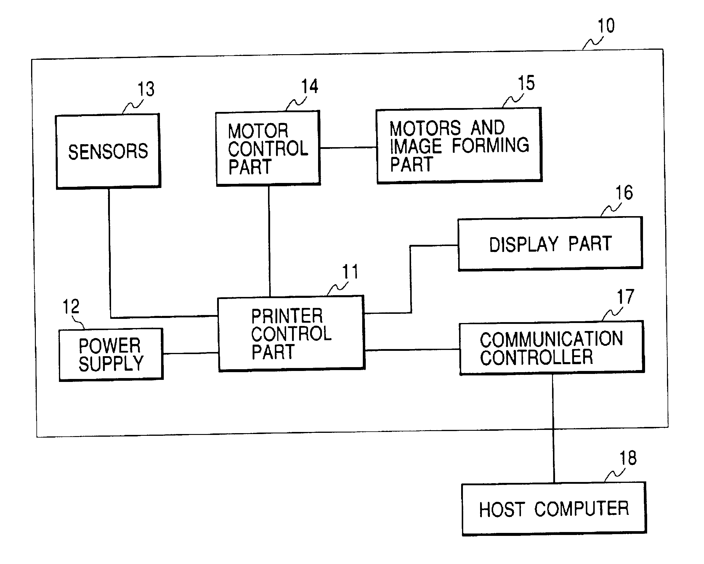
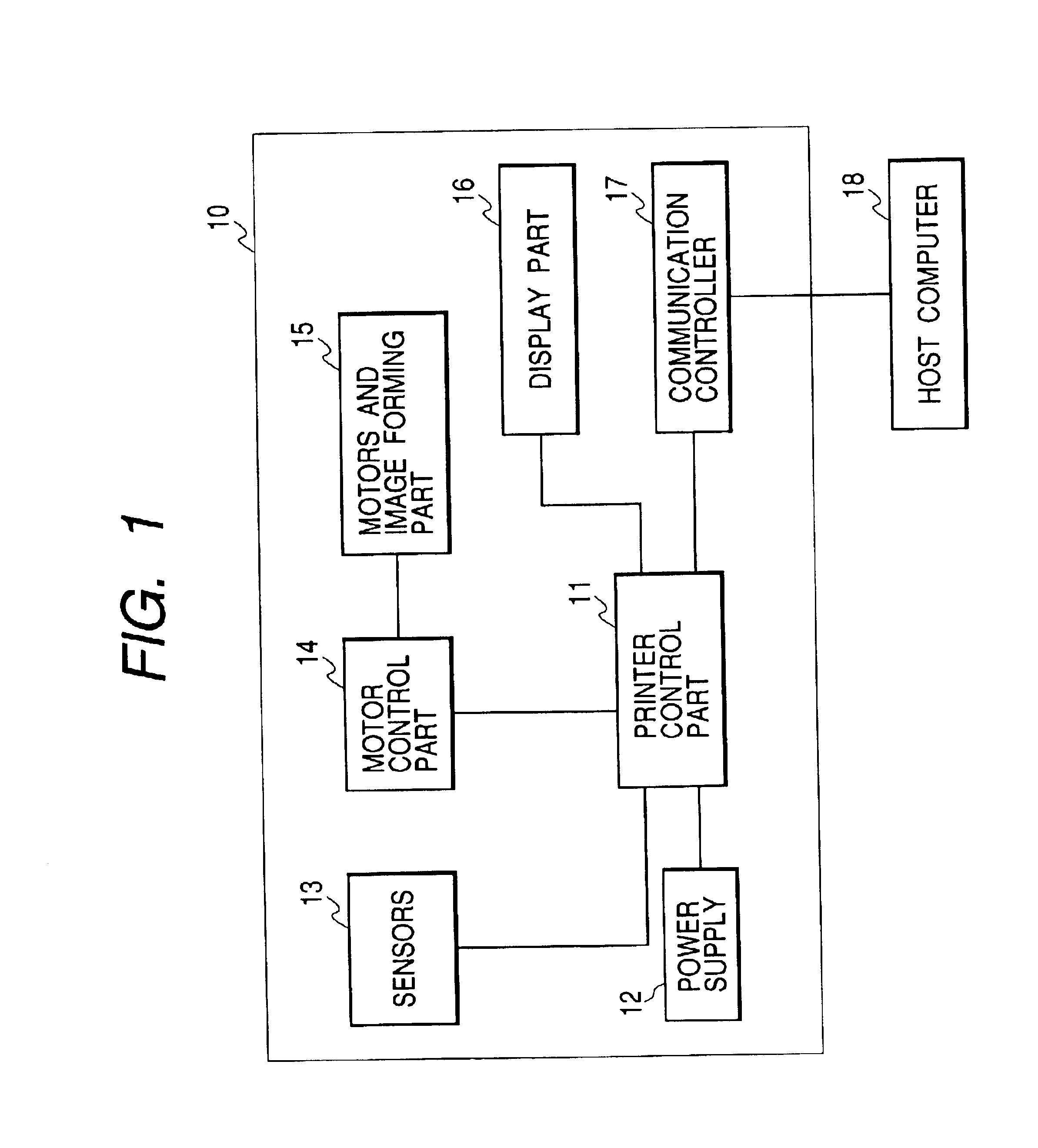
[0061]FIG. 1 shows a schematic configuration of a control system of an image forming apparatus in accordance with the present invention.

[0062]In FIG. 1, reference numeral 10 denotes a printer functioning as an image forming apparatus.

[0063]Reference numeral 11 denotes a printer control part for controlling each device in the printer 10.

[0064]Reference numeral 12 denotes a power supply for supplying power to each device in the printer 10.

[0065]Reference numeral 13 denotes sensors for detecting a state of each part in the printer 10.

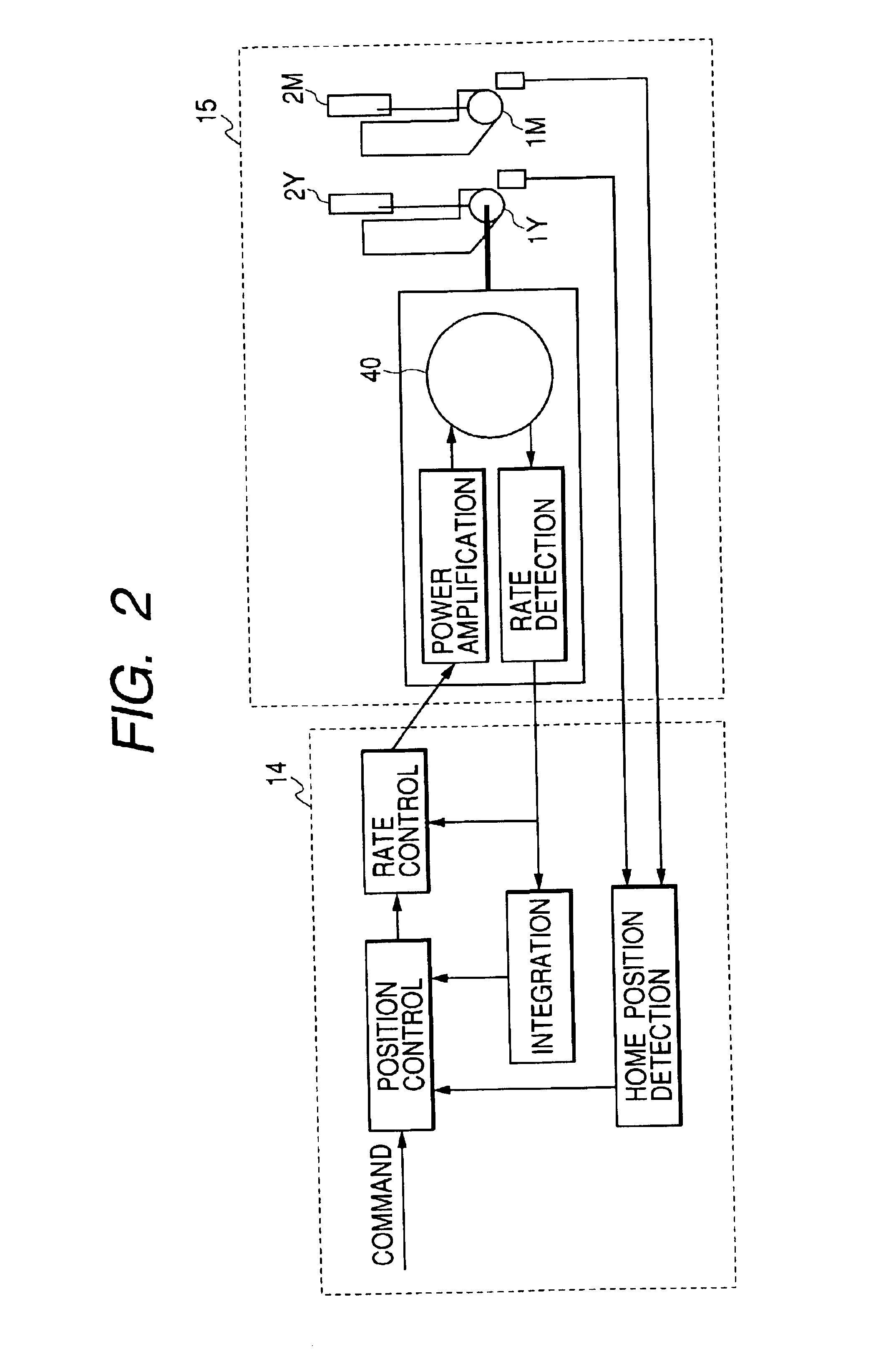
[0066]Reference numeral 14 denotes a motor control part functioning as a motor control means for controlling motors according to an instruction of the printer control part 11.

[0067]Reference numeral 15 denotes motors and an image forming part in the printer 10.

[0068]Reference numeral 16 denotes a display part for informing a user of an operation state of the printer 10.

[0069]Reference numeral 17 denotes a communication controller for cont...

second embodiment

(Second embodiment)

[0112]A second embodiment of the present invention will be described.

[0113]Since a configuration of the motors and the image forming part 15 and a schematic configuration of a control system of the second embodiment are identical to those in the first embodiment, description of them will be omitted.

[0114]The second embodiment is different from the first embodiment in that, when the DC brushless motors 40 are started up and the DC brushless motors 40 in operation are stopped, position control is not performed and the DC brushless motors 40 are controlled only by rate control.

[0115]Operation of this circuit will be described based on FIGS. 8 and 9.

[0116]When startup of the DC brushless motors 40 is instructed from the printer control part 11 (S801), the motor control part 14 applies rate control to each DC brushless motor 40, renews the command of rate in accordance with the fixed acceleration curve to accelerate each DC brushless motor 40 so as to minimize the rela...

third embodiment

(Third embodiment)

[0131]A third embodiment of the present invention will be described.

[0132]Since a configuration of the motors and the image forming part 15 and a schematic configuration of a control system of the third embodiment are identical as those in the first embodiment, descriptions on them will be omitted.

[0133]The third embodiment is different from the first embodiment in that the motor control part 14 compares the home position signal of each of the rotation bodies 1Y, 1M, 1C and 1K with an independent signal separate from the home position signals of the rotation bodies 1Y, 1M, 1C and 1K, for example, a motor rate ready signal indicating that all the CD brushless motors 40 have reached a target rate, as a reference and calculates the position error information of the DC brushless motors 40.

[0134]Operation of this circuit will be described based on FIGS. 10 and 11.

[0135]When startup of the DC brushless motors 40 is instructed from the printer control part 11 (S1001), the...


PUM


Abstract

An image forming apparatus is provided, which is capable of performing phase control of rotation bodies inexpensively and accurately and is capable of reducing time until completion of phase adjustment at the time of a print operation to prevent first print time from becoming long. This image forming apparatus includes a device for detecting a home position of rotation bodies, a motor, and a motor control device for controlling the motor by a software servo, in which said motor control device has a position control function with respect to the motor.

Description

BACKGROUND OF THE INVENTION[0001]1. Field of the Invention[0002]The present invention relates to an image forming apparatus, for example, an image forming apparatus of an electrophotographic system.[0003]2. Description of Related Art[0004]An example of a conventional image forming apparatus will be described with reference to FIGS. 12 and 13.[0005]FIG. 12 is a view illustrating motors and an image forming part. FIG. 13 is a view illustrating a DC brushless motor and its vicinities.[0006]FIG. 12 shows a multicolor image forming apparatus provided with motors and rotation bodies for four colors, namely, yellow Y, magenta M, cyan C, and black K. In FIG. 12, reference symbols 1Y, 1M, 1C and 1K denote the rotation bodies such as photosensitive drums functioning as developing units for forming and developing electrostatic latent images (1Y, 1M, 1C and 1K denote the rotation bodies for Y, M, C and K, respectively), and reference symbols 6Y, 6M, 6C and 6K denote the motors for driving the r...

Claims


Application Information

Patent Timeline
IPC IPC(8): H02P1/54G03G21/14G03G15/00G03G15/01G03G15/08
CPCG03G15/0194H02P6/085H02P6/04G03G2215/0119
Inventor KAMEYAMA, SHIGERU
Owner CANON KK
Why Eureka
Try Eureka