Electromagnetic starter switch

a starter switch and electric technology, applied in the direction of engine starters, bridges, machines/engines, etc., can solve the problem of requiring a proportionate number of assembly man-hours, and achieve the effect of reducing assembly man-hours

Active Publication Date: 2006-05-02
MITSUBISHI ELECTRIC CORP
View PDF7 Cites 38 Cited by
  • Summary
  • Abstract
  • Description
  • Claims
  • Application Information

AI Technical Summary

Benefits of technology

[0010]Using an electromagnetic starter switch according to the present invention, assembly man-hours are reduced.

Problems solved by technology

In an electromagnetic starter switch having the above configuration, because the main fixed contact is mounted to a main switch cover, and the auxiliary fixed contact is mounted to an auxiliary switch cover, one problem has been that the main switch cover and the auxiliary switch cover must each be mounted such that a fixed contact faces its respective movable contact, requiring a proportionate number of assembly man-hours.

Method used


Image

  • Electromagnetic starter switch
  • Electromagnetic starter switch
  • Electromagnetic starter switch

Examples


embodiment 1

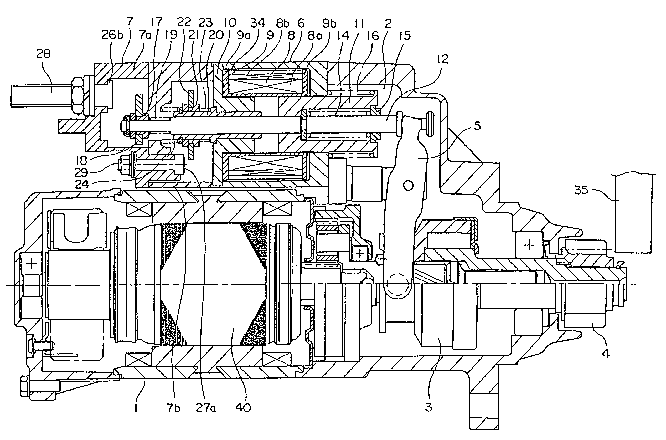
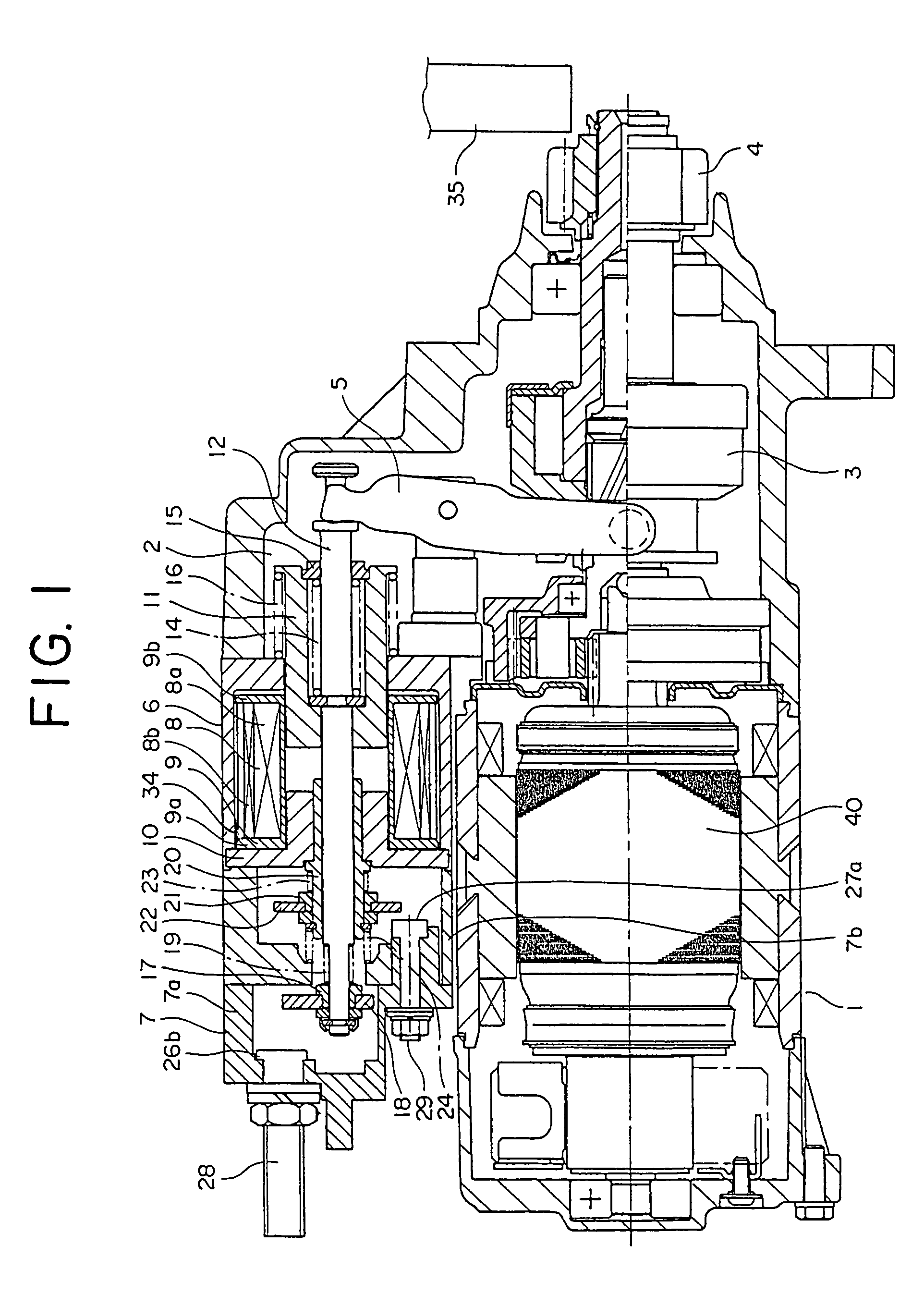
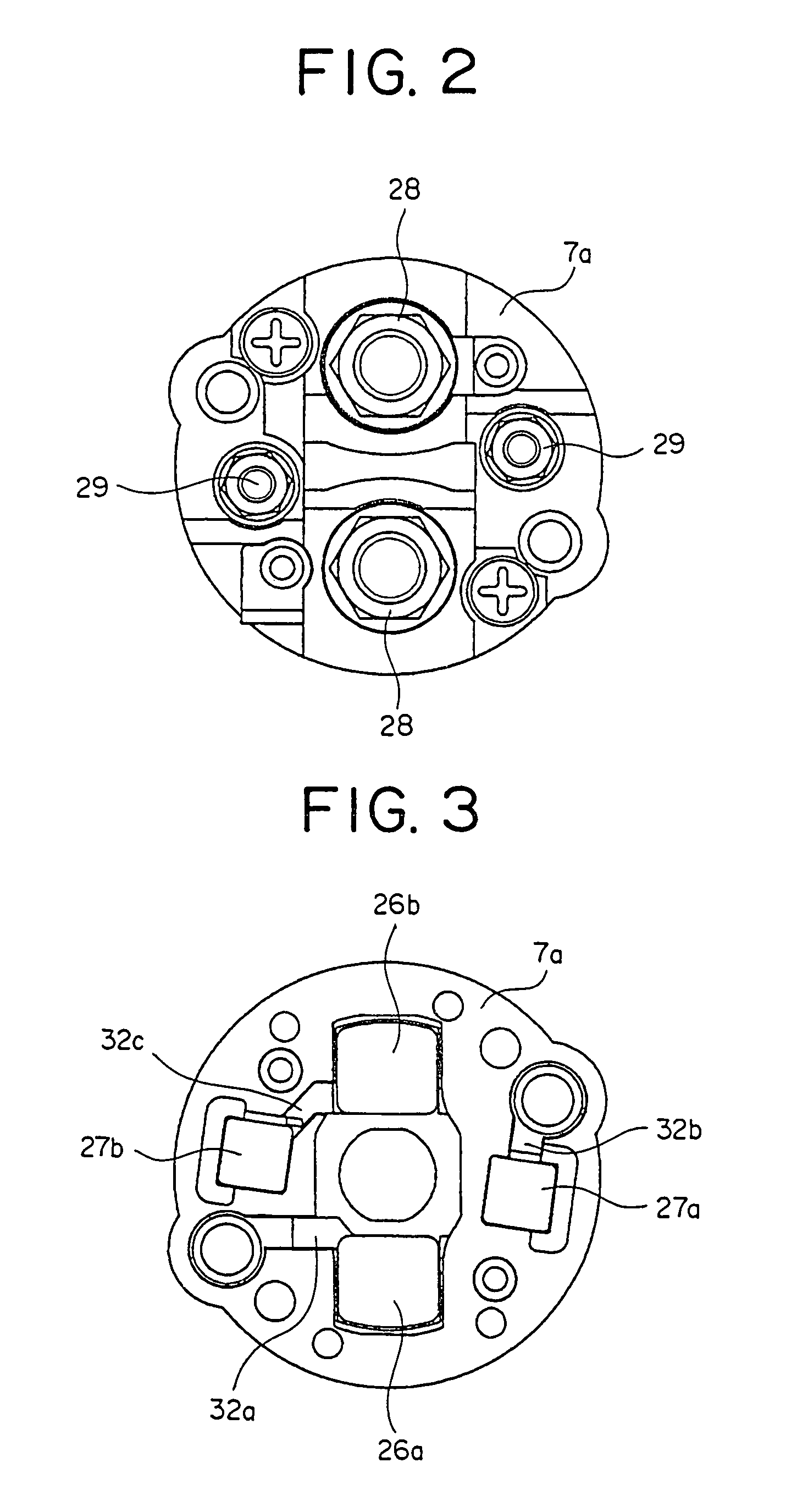
[0017]FIG. 1 is a cross section showing a starter according to Embodiment 1 of the present invention, FIG. 2 is a diagram showing a main switch cover 7a from FIG. 1 when viewed from a left side, and FIG. 3 is a rear end elevation of the main switch cover 7a in FIG. 2.

[0018]This starter includes: a motor 1; an electromagnetic starter switch (hereinafter abbreviated to “electromagnetic switch”) 2 switching on and off passage of electric current to the motor 1; a clutch 3 that is movable in an axial direction along a shaft of the motor 1; a pinion gear 4 linked to the clutch 3 and rotating with the clutch 3; and a lever 5 rotatably disposed between the electromagnetic switch 2 and the clutch 3.

[0019]In the electromagnetic switch 2, a switch cover 7 is connected to an opening portion of a cylindrical solenoid case 6.

[0020]A cylindrical bobbin 9 having first and second flanges 9a and 9b on two end portions is disposed inside the solenoid case 6. Coils 8 constituted by a primary coil 8a, ...


PUM


Abstract

An electromagnetic starter switch in which a voltage from a power source is depressed by a resistor and applied to a motor by an auxiliary movable contact coming into contact with a first auxiliary fixed contact and a second auxiliary fixed contact before a pinion gear intermeshes with a ring gear, and the voltage from the power source is subsequently applied to the motor without modification by the main movable contact also coming into contact with a first main fixed contact and a second main fixed contact after the pinion gear intermeshes with the ring gear, wherein: the first main fixed contact, the second main fixed contact, the first auxiliary fixed contact, and the second auxiliary fixed contact are disposed on a main switch cover.

Description

BACKGROUND OF THE INVENTION[0001]1. Field of the Invention[0002]The present invention relates to an electromagnetic starter switch for starting an internal combustion engine by means of a pinion gear driven by a motor.[0003]2. Description of the Related Art[0004]Conventionally, in electromagnetic switches installed in auxiliary rotating starters, in order to control action of a motor during starting so as to be divided into two phases, there is provided: a main fixed contact; a main movable contact coming into contact with the main fixed contact; an auxiliary fixed contact; and an auxiliary movable contact coming into contact with the auxiliary fixed contact, and a resistor is installed in series in a circuit formed when the auxiliary movable contact comes into contact with the auxiliary fixed contact such that an electric current from a battery flows through this closed circuit to an armature of the motor, rotating the armature at low speed to engage a pinion fixed to a shaft of th...

Claims


Application Information

Patent Timeline
Patent Type & Authority Patents(United States)
IPC IPC(8): H01H67/02
CPCF02N15/062H01H50/543F02N11/00F02D2400/18F02D2400/21H01H51/065E01D19/02E02B3/02
Inventor KUSUMOTO, KEIICHIYAMAUCHI, HAYATOKIMURA, MOTOAKI
Owner MITSUBISHI ELECTRIC CORP
Why Eureka
Try Eureka