Method and system for resource sharing between demodulating paths of a rake receiver

a resource sharing and rake receiver technology, applied in the field of mobile communications, can solve the problems of increasing the depth of the fifo memory for storing data, increasing the size and complexity of the rake receiver, so as to increase the number of demodulating branches and reduce the number of circuits. , the effect of high data rate communication

Inactive Publication Date: 2006-05-02
SAMSUNG ELECTRONICS CO LTD
View PDF3 Cites 7 Cited by
  • Summary
  • Abstract
  • Description
  • Claims
  • Application Information

AI Technical Summary

Benefits of technology

[0011]The present invention provides a rake receiver for high data rate communications systems that is able to share resources between demodulating branches without using independent hardware resources for each finger. That is, the rake receiver of the present invention uses less circuitry while increasing the number of demodulating branches, thereby having a significantly smaller size, being able to track more demodulating paths for increasing performance, and being less complex as compared to conventional rake receivers for high data rate communications systems.

Problems solved by technology

Thus, the depth of the FIFO memory for storing data is increased and the architecture or structure of the rake receiver for third high data rate communications systems becomes complex.
Hence, there is an increase in the size and complexity of the rake receiver.

Method used


Image

  • Method and system for resource sharing between demodulating paths of a rake receiver
  • Method and system for resource sharing between demodulating paths of a rake receiver
  • Method and system for resource sharing between demodulating paths of a rake receiver

Examples


first embodiment

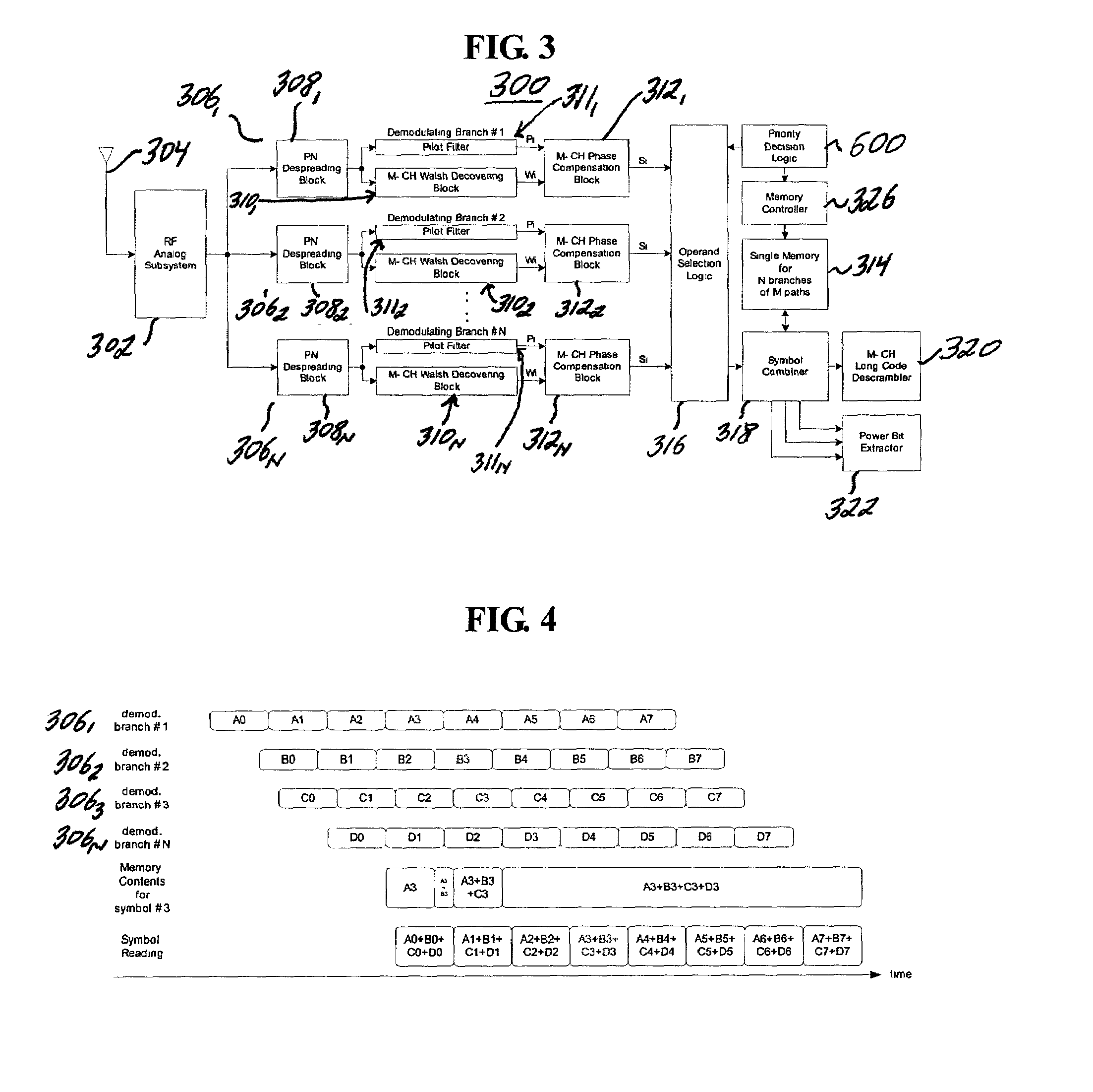
[0033]With reference to FIG. 3, there is shown a rake receiver according to the first embodiment designated generally by reference numeral 300. The rake receiver 300 includes an RF analog subsystem block 302, which converts signals received from an antenna 304 to digital data and feeds the converted digital data to each finger 3061–306N. In each finger 3061–306N, symbols transmitted from the transmitter are despreaded by PN despreading blocks 3081–308N.

[0034]The demodulated symbols Wi and the estimated pilot channel gains Pi are provided by Walsh decovering blocks 3101–310N and pilot filter blocks 3111–311N respectively, and they are transferred to phase compensation blocks 3121–312N. Therefore, the final output of each demodulating finger 3061–306N is phase-compensated symbol data. The symbol data belong to different physical channels and the data rate of each channel is variable according to circumstances. In the physical channels, each channel is identified by corresponding Walsh...

second embodiment

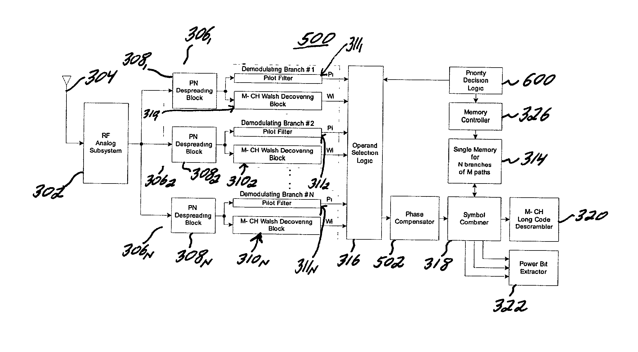
[0057]With reference to FIG. 5, there is shown a rake receiver structure according to the second embodiment designated generally by reference numeral 500. The rake receiver structure 500 includes the RF analog subsystem block 302, which converts signals received from the antenna 304 to digital data and feeds the converted digital data to each finger 3061–306N. In each finger 3061306N, symbols transmitted from the transmitter are despreaded by the PN despreading blocks 3081–308N. The demodulated symbols Wi and the estimated pilot channel gains Pi are provided by Walsh decovering blocks 3101–310N and pilot filter blocks 3111–311N, and they are transferred to the operand selection logic block 316. The output of each finger 3061–306N is not a symbol but a correlator output for each channel and an estimated pilot channel gain.

[0058]In the same manner as for the case of sharing only the time deskew buffer 314 of the first embodiment, the priority decision logic block 600 selects one of th...


PUM


Abstract

A rake receiver for high data rate communications systems is provided that is able to share resources between demodulating branches without using independent hardware resources for each finger. The rake receiver of the present invention uses less circuitry while keeping functional equivalence, and it requires relatively smaller additional area when increasing the number of demodulating branches, thereby having a significantly smaller size, being able to track more demodulating paths for increasing performance, and being less complex as compared to conventional rake receivers for high data rate communications systems.

Description

BACKGROUND OF THE INVENTION[0001]1. Technical Field[0002]The present disclosure relates generally to mobile communications, and more particularly, to a method and system for resource sharing between demodulating paths of a rake receiver. In general, a rake receiver combines signals that are transmitted on a channel in different paths from a transmitter and arrive at different time points in order to increase reception performance through path diversity.[0003]2. Background of the Related Art[0004]As shown in FIGS. 1 and 2, a conventional rake receiver 100 includes an RF analog subsystem block 102, which converts signals received from an antenna 104 to digital data and feeds the converted digital data to each finger 1061–106N. In each finger 1061–106N, symbols transmitted from the transmitter are demodulated by PN despreading blocks 1081–108N.[0005]The demodulated symbols Wi and the estimated pilot channel gains Pi are provided by Walsh decovering blocks 1101–110N and pilot filter blo...

Claims


Application Information

Patent Timeline
Patent Type & Authority Patents(United States)
IPC IPC(8): H04B1/69H04B1/10H04B1/7115H04B1/7117
CPCH04B1/7115H04B2201/7071H04B1/7117
Inventor HAN, SUNG-CHUL
Owner SAMSUNG ELECTRONICS CO LTD
Why Eureka
Try Eureka