Pattern recognition apparatus for detecting predetermined pattern contained in input signal

a pattern recognition and input signal technology, applied in the field of pattern recognition apparatus for detecting predetermined patterns in input signals, can solve the problems of inability to read the results of processing, not being able to spatially integrate the results of areas, and being unable to obtain plural process hierarchical processing by parallel process with other plural processor units, etc., to achieve the effect of reading the result of each process and avoiding the problem of affecting the quality of the outpu

Active Publication Date: 2006-05-02
CANON KK
View PDF17 Cites 77 Cited by
  • Summary
  • Abstract
  • Description
  • Claims
  • Application Information

AI Technical Summary

Benefits of technology

[0011]In consideration of the foregoing, the object of the present invention is to provide a pattern recognition apparatus capable, with a single circuit configuration not requiring complex wirings, of executing hierarchical processing such as parallel processing with plural process units on the plural results obtained by processing in plural processors, also of spatially integrating the results of processing in the processors, and easily reading the result of each process.

Problems solved by technology

Among such conventional technologies, the object recognition apparatus disclosed in the Japanese Patent Application Laid-Open No. 6-6793 is capable of processing in several stages for the areas assigned to the image processor units and for the further divided smaller areas back to the original areas, but is incapable of hierarchical processing by parallel process' with other plural processor units for the obtained plural process results.
It is also not capable of reading the results of processing, nor capable of spatially integrating the results from the areas.
Also the hierarchical neural network disclosed in the Japanese Patent No. 2679730 is associated with a drawback that the types of the practically realizable processes are quite limited because of the absence of a unit for variably and arbitrarily controlling the interlayer coupling.

Method used


Image

  • Pattern recognition apparatus for detecting predetermined pattern contained in input signal
  • Pattern recognition apparatus for detecting predetermined pattern contained in input signal
  • Pattern recognition apparatus for detecting predetermined pattern contained in input signal

Examples


first embodiment

(First Embodiment)

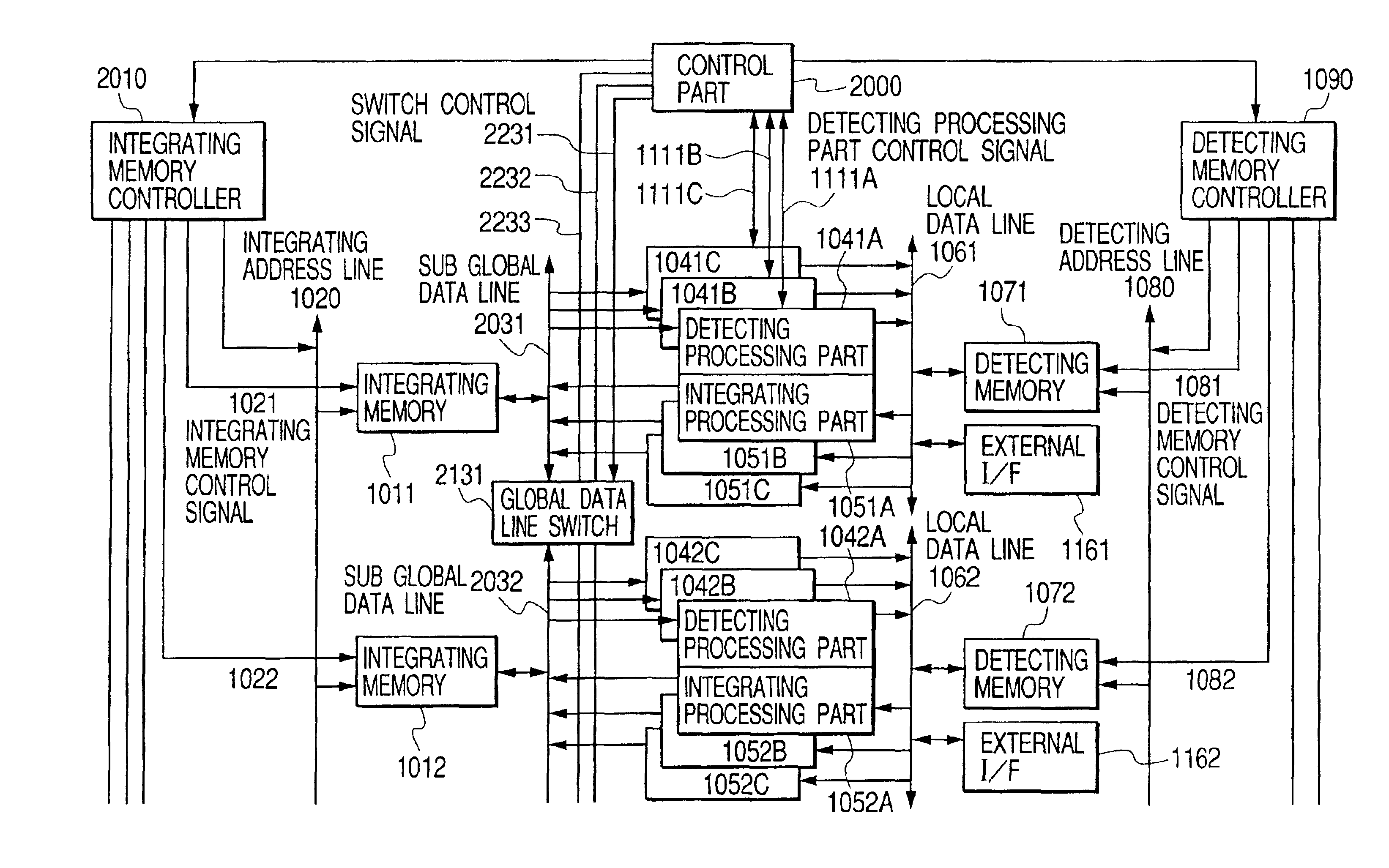
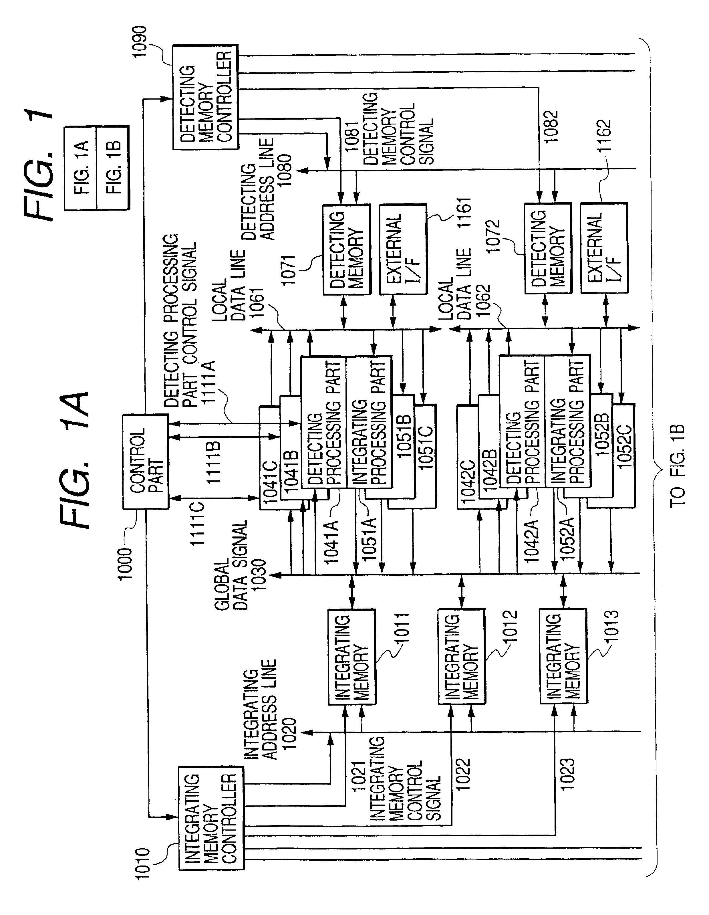
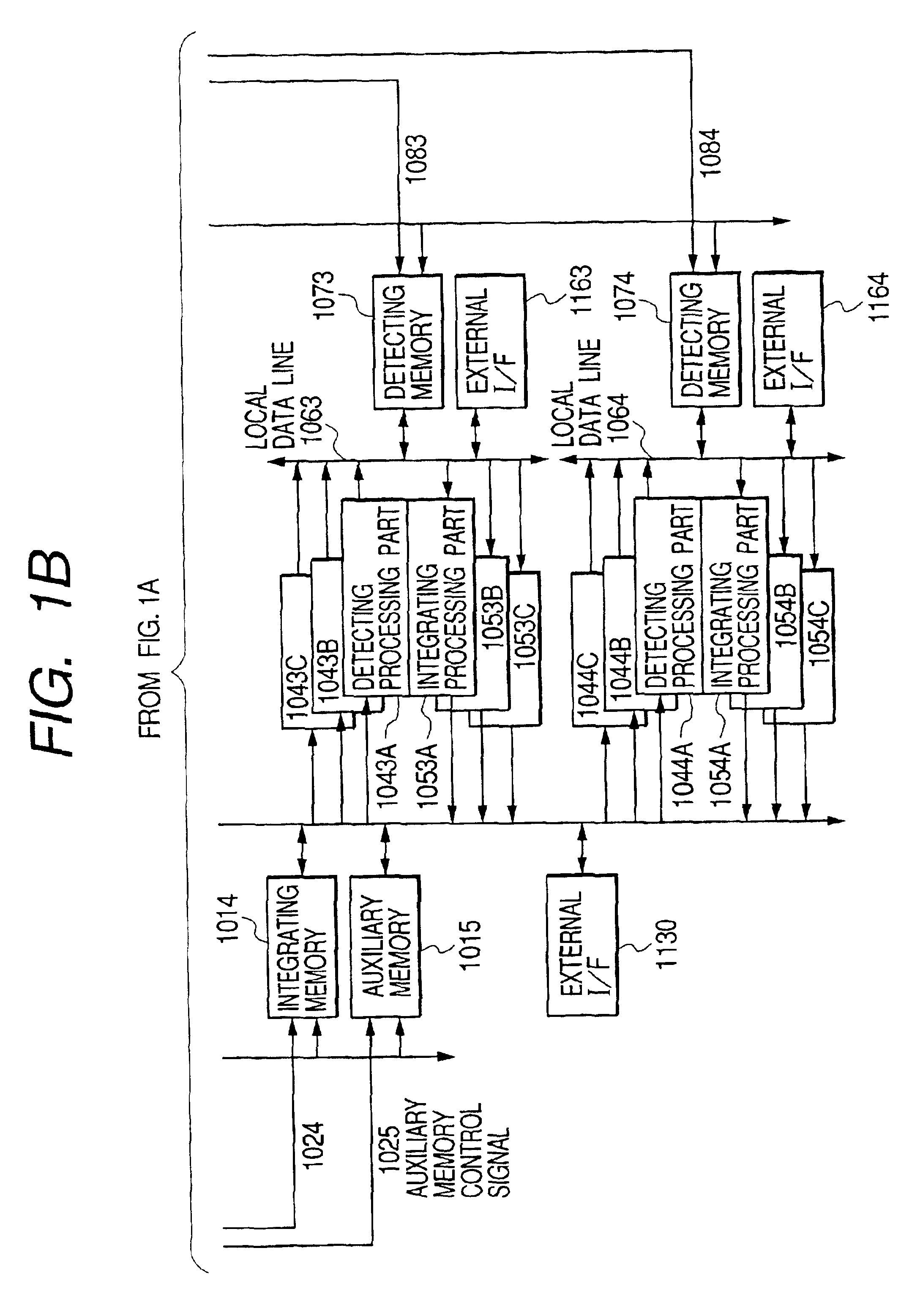
[0028]FIGS. 1A and 1B are views showing the configuration of the present embodiment.

[0029]Referring to FIGS. 1A and 1B, a control part 1000 is a unit for controlling the entire circuit, communicating with an integrating memory controller 1010 to be explained later, detecting process (processing) parts 1041A to 1044C, integrating process (processing) parts 1051A to 1054C and a detection memory controller 1090 and controlling these parts based on a recognition algorithm to be used thereby executing recognition.

[0030]The integrating memory controller 1010 controls integrating memories 1011 to 1014 and an auxiliary memory 1015 thereby outputting data from these memories to a global data line 1030 and writing the data on the global data line 1030 into the integrating memories 1011 to 1014 or the auxiliary memory 1015. More specifically, it executes the aforementioned operations by outputting an address to an integrating address line 1020 and controlling integrating memo...

second embodiment

(Second Embodiment)

[0081]FIGS. 6A and 6B show the configuration of the present embodiment, wherein components equivalent to those in FIGS. 1A and 1B are represented by like numbers. In comparison with the first embodiment, the new components in FIGS. 6A and 6B are a control part 2000, an integrating memory controller 2010, sub-global data lines 2031 to 2034, global data line switches 2131 to 2133, and switch control lines 2231 to 2233.

[0082]In contrast to the first embodiment in which the global data bus 1030 shown in FIGS. 1A and 1B are connected to all the integrating memories 1011 to 1014, the auxiliary memory 1015, all the detecting process parts 1041A to 1044C and all the integrating process parts 1051A to 1054C, a sub-global data line in the present embodiment is connected to an integrating memory, plural detecting process parts and plural integrating process parts or auxiliary memories. The number of the detecting process parts and the integrating process parts connected to a...

third embodiment

(Third Embodiment)

[0088]FIGS. 8A and 8B show the configuration of the present embodiment, wherein components equivalent to those in FIGS. 1A and 1B are represented by like numbers. In comparison with the first embodiment, the new components in FIGS. 8A and 8B are a control part 3000, an integrating memory controller 3010, global data lines 3031 to 3035, and detecting process parts 3041A to 3044C.

[0089]In contrast to the first embodiment in which the global data bus 1030 shown in FIGS. 1A and 1B are connected to all the integrating memories 1011 to 1014, the auxiliary memory 1015, all the detecting process parts 1041A to 1044C and all the integrating process parts 1041A to 1044C and all the integrating process parts 1051A to 1054C, a global data line in the present embodiment is connected to an integrating memory or the auxiliary memory, all the detecting process parts and plural integrating process parts. The number of the integrating process parts connected to a global data line is...


PUM


Abstract

A pattern recognition apparatus for detecting a predetermined pattern contained in an input signal is provided with plural detecting processing parts and for detecting respectively different features for a same input, plural integrating processing parts for spatially integrating, for each process results, the features detected by the plural detecting processing parts, plural detecting memories for retaining the process results of the detecting processing parts, plural integrating memories for retaining the process results of the integrating processing parts, a global data line 1030 to which all the predetermined detecting processing parts and all the predetermined integrating memories are connected at a certain timing, and plural local data lines each of which is connected to a predetermined set of the detecting processing parts, the integrating processing parts and the detecting memory.

Description

BACKGROUND OF THE INVENTION[0001]1. Field of the Invention[0002]The present invention relates to a circuit configuration of a pattern recognition apparatus for executing pattern recognition, detection of a specified object etc. by parallel operation of a neural network or the like.[0003]2. Description of Related Art[0004]Conventionally, the process of image recognition or voice recognition is divided into a type of executing in succession a recognition process algorithm specified for a certain object of recognition as a computer software, and a type of executing such algorithm by an exclusive parallel image processor (SIMD, MIMD machine etc.).[0005]As for the latter, the Japanese Patent Application Laid-Open No. 6-6793 discloses an object recognition apparatus in which plural image processor units are employed to execute the process by DSP's provided in such processor units, and the obtained plural results are transferred to another unit for executing recognition of the object. For ...

Claims


Application Information

Patent Timeline
Patent Type & Authority Patents(United States)
IPC IPC(8): G06K9/00G06K9/54G06N3/00G06K9/46G06K9/66G06N3/06G06T7/00
CPCG06K9/4628G06K9/00973G06V10/94G06V10/454
Inventor MORI, KATSUHIKOMATSUGU, MASAKAZUNOMURA, OSAMU
Owner CANON KK
Why Eureka
Try Eureka