Portable laser transceiver

a laser transceiver and portability technology, applied in the field of transceivers, can solve the problems of affecting the transmission speed of laser signals, physical and practical limitations detracting from such solutions, etc., and achieve the effect of convenient portability

Inactive Publication Date: 2006-05-02
LASER DIODE SYST
View PDF10 Cites 3 Cited by
  • Summary
  • Abstract
  • Description
  • Claims
  • Application Information

AI Technical Summary

Benefits of technology

[0012]In a seventh separate aspect of the present invention, a portable transceiver of ethernet signals includes an input for receiving such signals, a splitter and a plurality of lasers facing in parallel directions. Again, a Mangin mirror may be employed with an aperture f...

Problems solved by technology

Such flickering is highly disruptive to data transmission.
Oft...

Method used


Image

  • Portable laser transceiver
  • Portable laser transceiver
  • Portable laser transceiver

Examples


Embodiment Construction

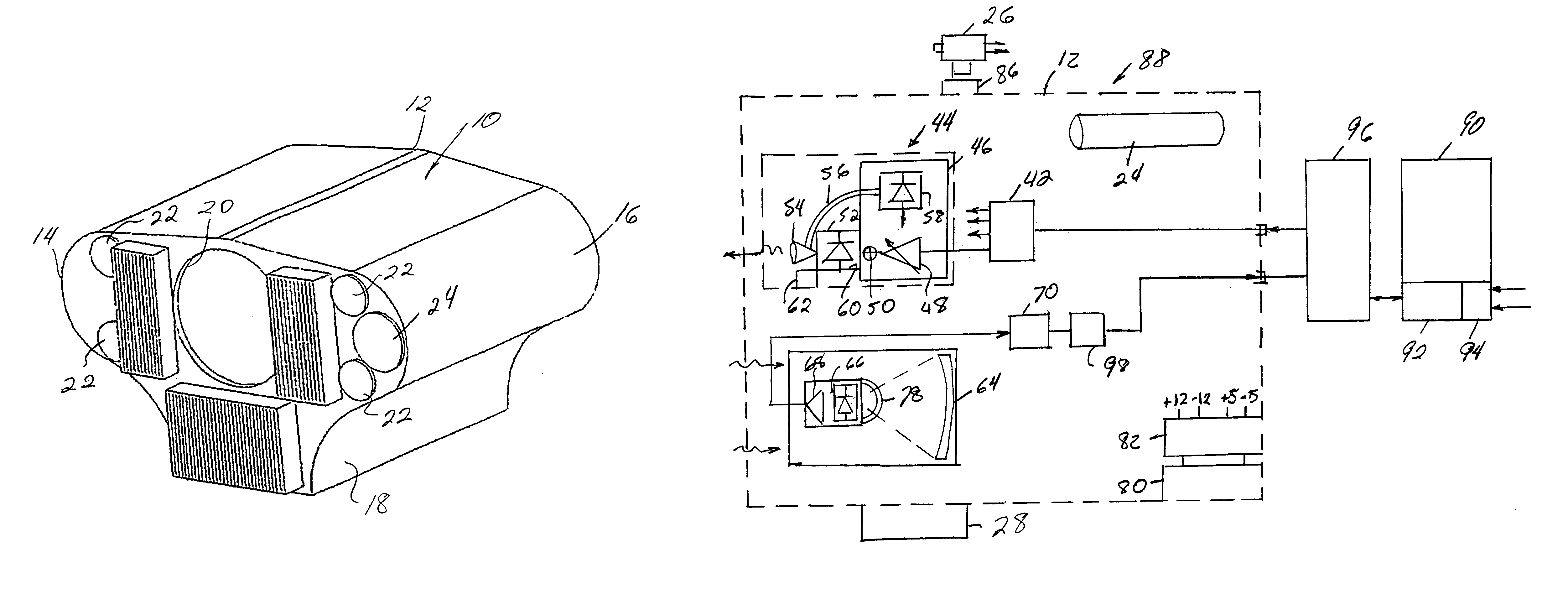
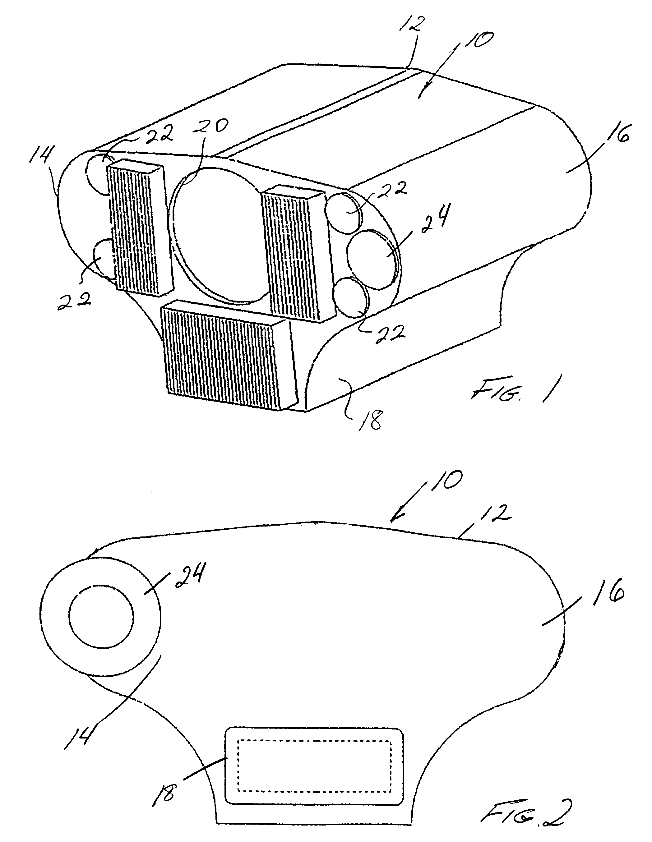
[0020]Turning in detail to the drawings, a portable transceiver 10 is illustrated as including a housing 12 having lateral lobes 14 and 16 such that the transceiver 10 may be manually held much as binoculars. A battery pack structure 18 depends centrally from the housing 12. It is also contemplated that the housing 12 may be modified such that a battery pack will be located outside of the housing and received by an accessory shoe much as a camera flash attachment. A receiving aperture 20 is located centrally in the front of the housing 12. Four laser apertures 22 are spaced about the receiving aperture 20. A visual sighting scope 24 extends fully through the housing 12 and is aligned with the lasers for aiming of the transceiver 10. The scope 24 may provide active or passive filters for enhancing detection of another transceiver with which communication is being established.

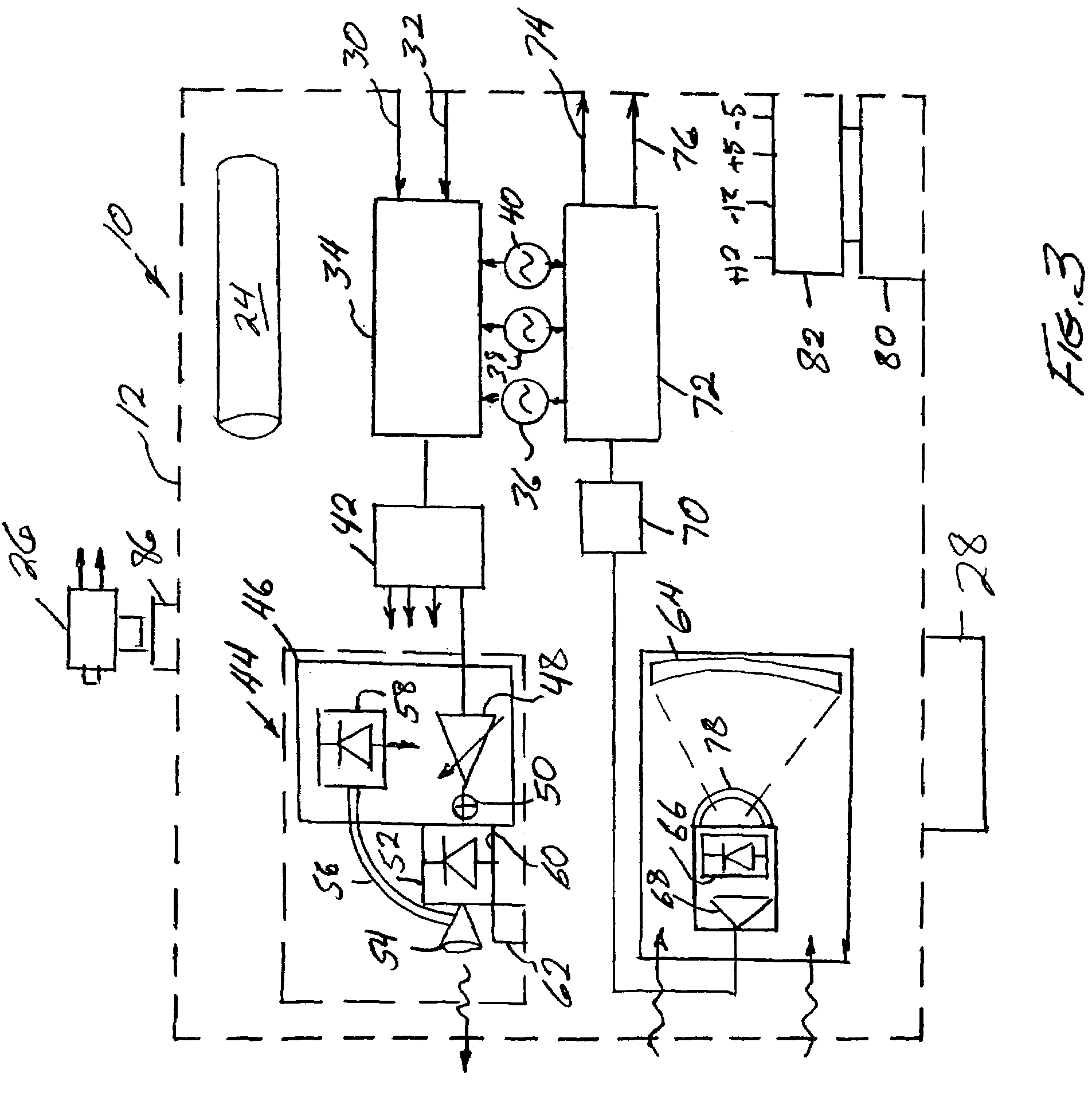
[0021]Accessories which may be employed with the transceiver 10 are illustrated schematically in FIGS. 3 and 4...


PUM


Abstract

A portable transceiver of one or more signals includes an input, frequency modulation, a splitter and a plurality of lasers in a transmitter module. A receiver module includes a Mangin mirror aligned with an input aperture. A photodiode receives the signal from the mirror for subsequent demodulation. An interference filter is arranged between the mirror and the photodiode. The filter is hemispherical, having a center of curvature at the focal point of the mirror. The transceiver may include a video camera and gyro-stabilizer accessories. A visual siting scope is aligned with the lasers and the receiver. A separate transceiver for ethernet input signals interfaces with a 10/100 ethernet switch and does not employ frequency modulation.

Description

BACKGROUND OF THE INVENTION[0001]The field of the present invention is transceivers using lasers as the communicating medium.[0002]A phenomenon referred to as scintillation causes the random fading of signals transmitted through the atmosphere. It is understood that the atmosphere is not homogeneous in that the index of refraction of air is not constant due to wind or turbulence. The transmission of a beam of light through the atmosphere is subject to these variations in the index of refraction such that the beam may be momentarily deflected from a straight path. With such deflection, an observer of the beam perceives the source to be flickering. Such flickering is highly disruptive to data transmission. A solution may be found in the increase in size of the apertures of the sending and receiving units. The intensity of the source can to a certain extent mitigate losses in transmission where the sensitivity of the receiver is not correspondingly decreased. Often, physical and practi...

Claims


Application Information

Patent Timeline
IPC IPC(8): H04B10/00
CPCH04B10/43
Inventor MECHERLE, GEORGE STEPHENHOLCOMB, TERRY LEE
Owner LASER DIODE SYST
Why Eureka
Try Eureka