
Low latency request dispatcher

a request dispatcher and low-latency technology, applied in the field of high-performance memory request dispatchers, can solve the problems of routers suffering performance degradation, routers failing to handle traffic at line rate, and general purpose processors cannot scale to meet these new demands, so as to reduce the overall latency of memory request and minimize the queue

Inactive Publication Date: 2006-05-02
JUMIPER NETWORKS INC
View PDF3 Cites 36 Cited by
  • Summary
  • Abstract
  • Description
  • Claims
  • Application Information

AI Technical Summary

Benefits of technology

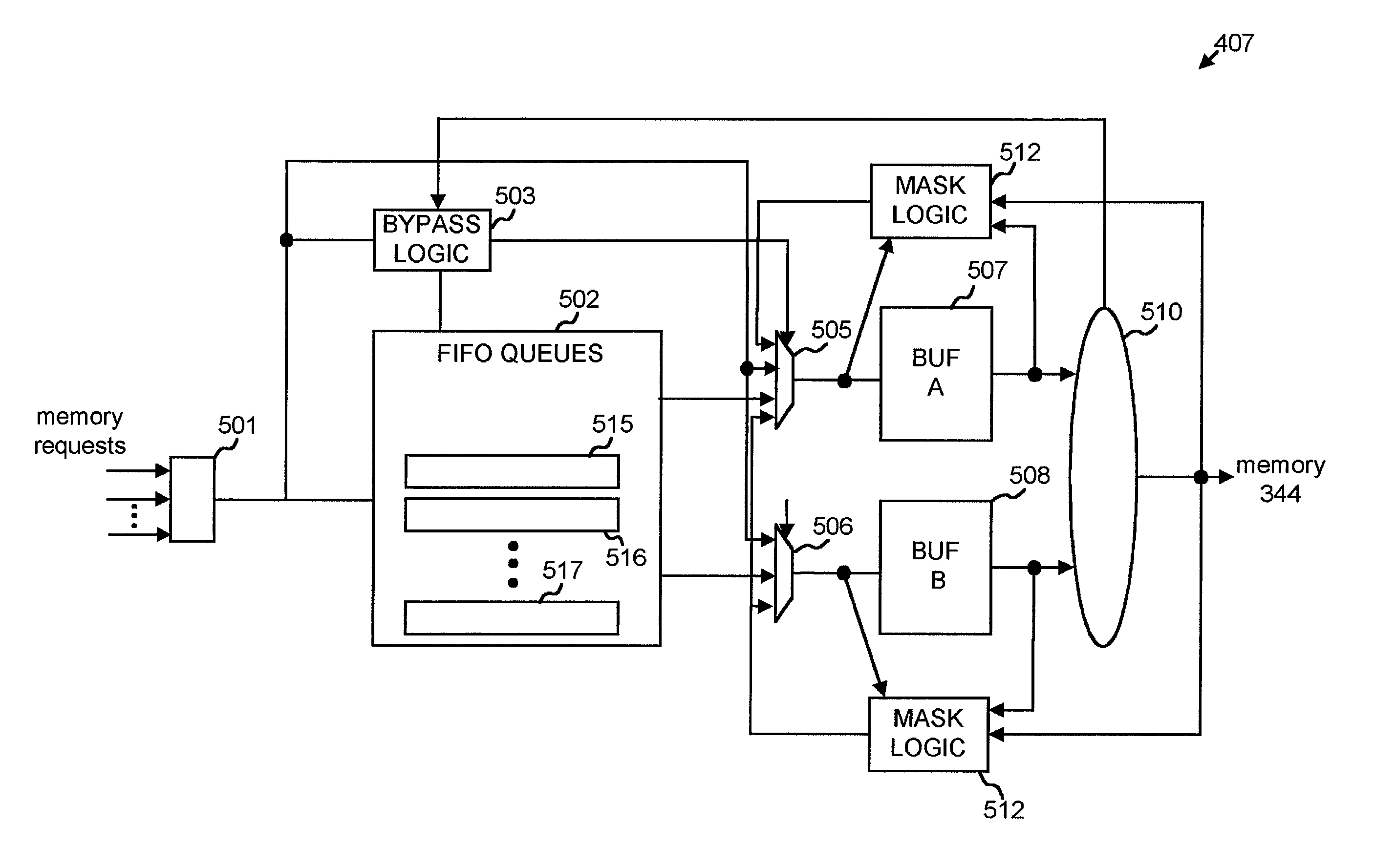
[0009]An arbiter processes memory requests in a first-in-first-out (FIFO) order using a queue and corresponding components that minimize latency of the queue. In this manner, overall memory request latency is reduced.
[0011]A method of masking latency in a queue is another aspect of the invention. The method includes receiving incoming data items for the queue and forwarding the incoming data items to a buffer when the queue is empty and the buffer is free to receive data items. Additionally, the method includes enqueuing the incoming data items to the queue when the queue contains data items or the buffer is not free to receive data items, and dequeuing data items from the queue to the buffer when the buffer is free to receive data items. Finally, the method includes transmitting the data items from the buffer as the output of the queue.

Problems solved by technology

As line rates and traffic volume increased, however, general purpose processors could not scale to meet these new demands.
For example, as functionality was added to the software, such as accounting and policing functionality, these routers suffered performance degradation.
In some instances, the routers failed to handle traffic at line rate when the new functionality was enabled.
In a high-performance router, the large number of packets received can translate into a heavy burden on the memory.
However, even with such high performance memories, processing a large number of memory requests may still cause system latency and thus slows down the operation of the router.

Method used


Image

  • Low latency request dispatcher
  • Low latency request dispatcher
  • Low latency request dispatcher

Examples


Embodiment Construction

[0023]The following detailed description of the invention refers to the accompanying drawings. The same reference numbers in different drawings may identify the same or similar elements. Also, the following detailed description does not limit the invention. Instead, the scope of the invention is defined by the appended claims and equivalents.

System Description

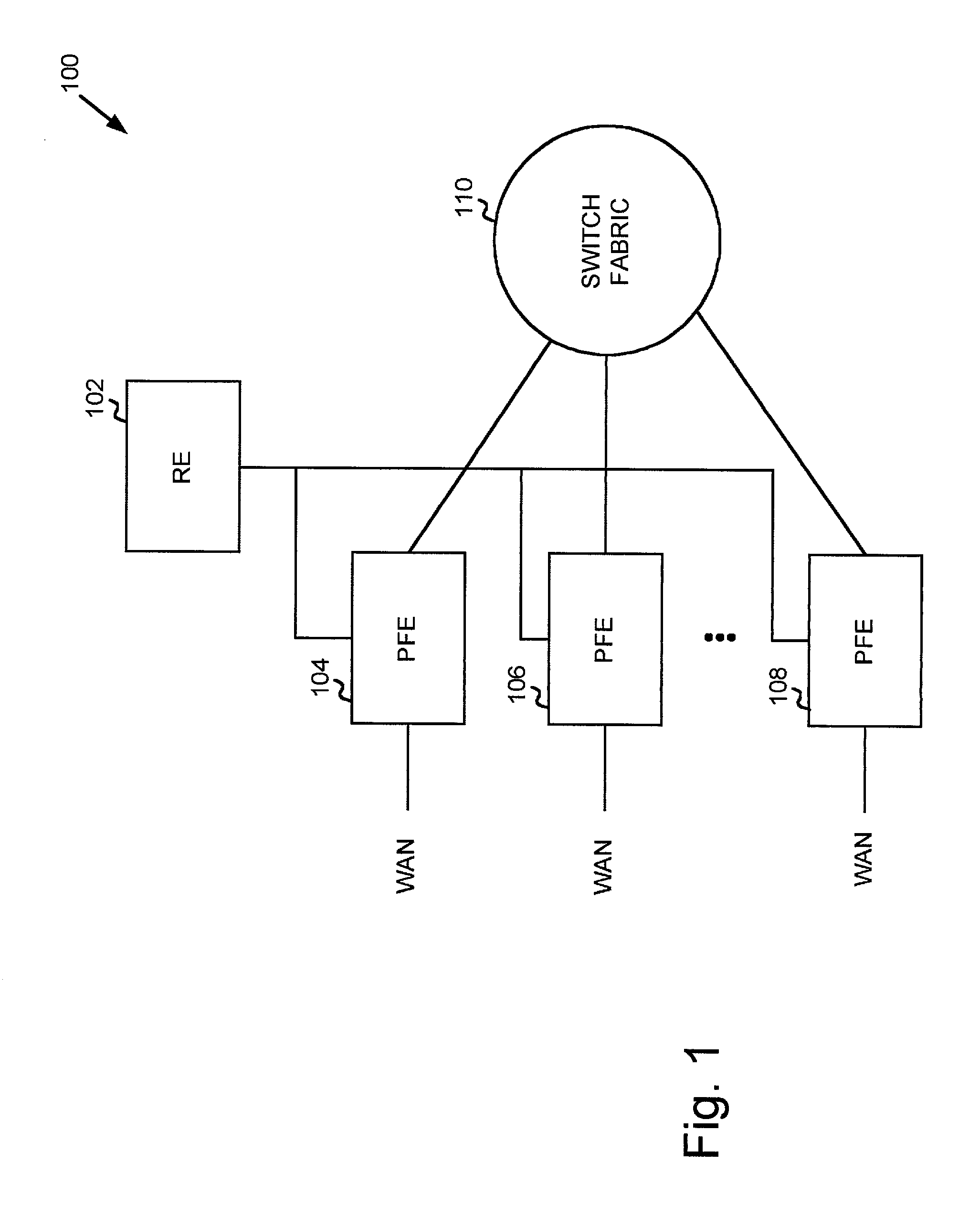
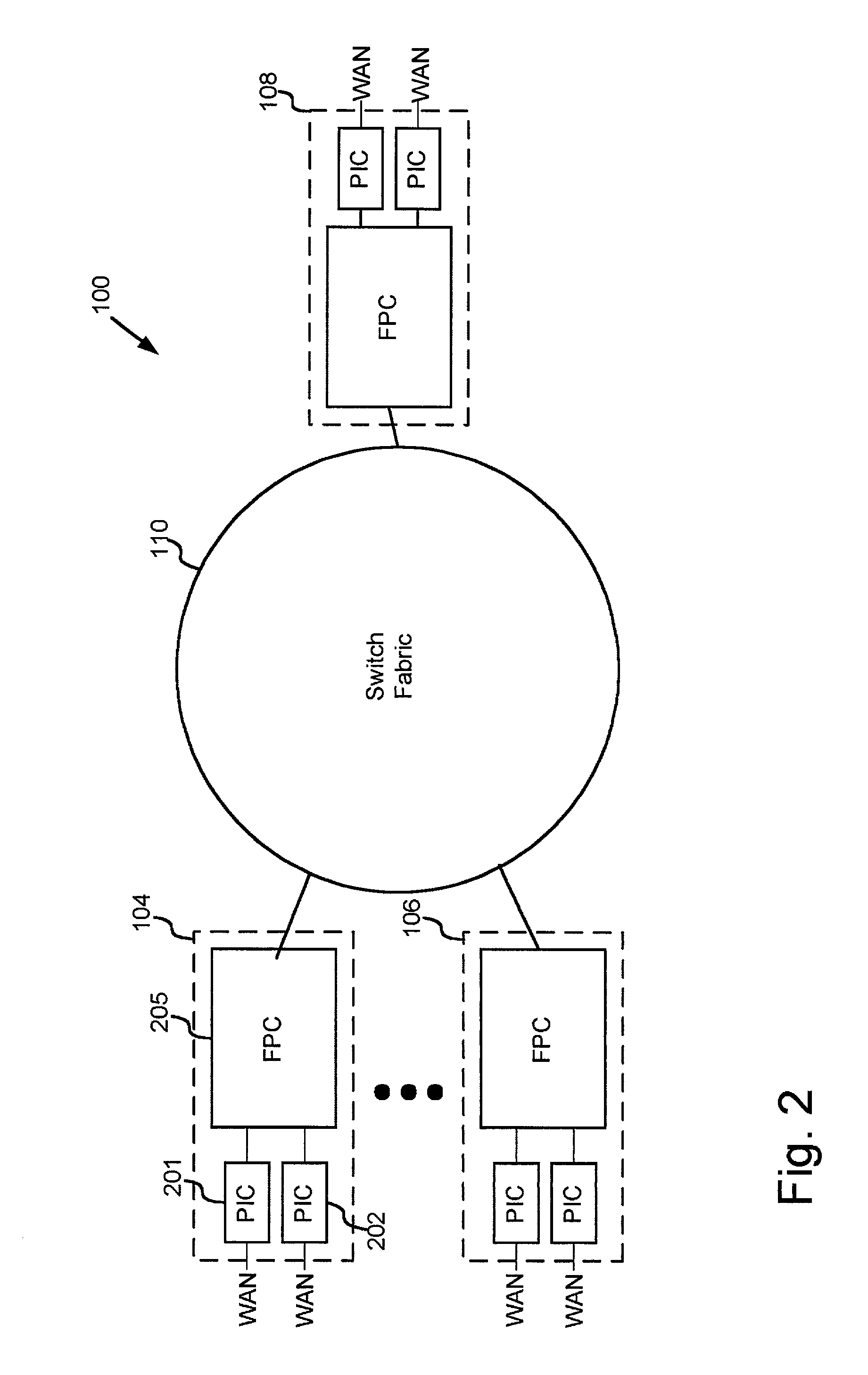
[0024]FIG. 1 is a block diagram illustrating an exemplary routing system 100 in which principles consistent with the invention may be implemented. System 100 includes packet forwarding engines (PFEs) 104, 106 . . . 108, a switch fabric 110, and a routing engine (RE) 102. System 100 receives one or more data streams from a physical link, processes the data streams to determine destination information, and transmits the data streams out on links in accordance with the destination information.

[0025]RE 102 performs high-level management functions for system 100. For example, RE 102 communicates with other networks and systems conne...


PUM


Abstract

A first-in-first-out (FIFO) queue optimized to reduce latency in dequeuing data items from the FIFO. In one implementation, a FIFO queue additionally includes buffers connected to the output of the FIFO queue and bypass logic. The buffers act as the final stages of the FIFO queue. The bypass logic causes input data items to bypass the FIFO and to go straight to the buffers when the buffers are able to receive data items and the FIFO queue is empty. In a second implementation, arbitration logic is coupled to the queue. The arbitration logic controls a multiplexer to output a predetermined number of data items from a number of final stages of the queue. In this second implementation, the arbitration logic gives higher priority to data items in later stages of the queue.

Description

BACKGROUND OF THE INVENTION[0001]A. Field of the Invention[0002]The present invention relates generally to arbitration, and more particularly, to a high performance memory request dispatcher.[0003]B. Description of Related Art[0004]Routers receive data on a physical media, such as optical fiber, analyze the data to determine its destination, and output the data on a physical media in accordance with the destination. Routers were initially designed using a general purpose processor executing large software programs. As line rates and traffic volume increased, however, general purpose processors could not scale to meet these new demands. For example, as functionality was added to the software, such as accounting and policing functionality, these routers suffered performance degradation. In some instances, the routers failed to handle traffic at line rate when the new functionality was enabled.[0005]To meet the new demands, purpose-built routers were designed. Purpose-built routers are...

Claims


Application Information

Patent Timeline
IPC IPC(8): G06F12/00
CPCG06F5/065G06F2207/3868
Inventor CHEN, DEVEREAUX C.ZIMMER, JEFFREY R.
Owner JUMIPER NETWORKS INC
Learn More