Method and apparatus for providing dynamic force sensations for force feedback computer applications

a technology of dynamic force sensation and computer application, which is applied in the direction of mechanical control devices, instruments, manual control with single controlling member, etc., can solve the problems of inability to cushion the jolt, the force sensation output of the device is often predefined, and the user cannot anticipate the collision

Inactive Publication Date: 2006-05-02
IMMERSION CORPORATION
View PDF281 Cites 99 Cited by
  • Summary
  • Abstract
  • Description
  • Claims
  • Application Information

AI Technical Summary

Benefits of technology

[0010]The present invention is directed to designing and controlling force sensations output by a force feedback interface device. A controlling host computer sends high-level host commands

Problems solved by technology

A current problem with the prior art force feedback interfaces is that force sensations output by the devices are often predefined, “canned”-sensations that are simply output by the interface device when instructed by the host computer.
While effective to relay the collision experience to some extent, this jolt may also be unsatisfying for the user, since the user has no way to affect the jolt based on the user's input during the jolt's duration.
For example, the user cannot, in anticipation of the collision, cushion the jolt caused by the impact by moving the joystick in the same direction as the jolt or moving the joystick in other ways.
Other force sensations provided by the prior art force feedback devices may be dependent on user input, but only in limited ways.
However, this is a crude, simplistic effect, for it fails to take into account undulations or waves in the swamp muck which the user may feel and which may cause the damping force to vary in magnitude and direction.
In addition, the user is unable to provide input or skill in changing the affects of the damping to achie

Method used


Image

  • Method and apparatus for providing dynamic force sensations for force feedback computer applications
  • Method and apparatus for providing dynamic force sensations for force feedback computer applications
  • Method and apparatus for providing dynamic force sensations for force feedback computer applications

Examples


Embodiment Construction

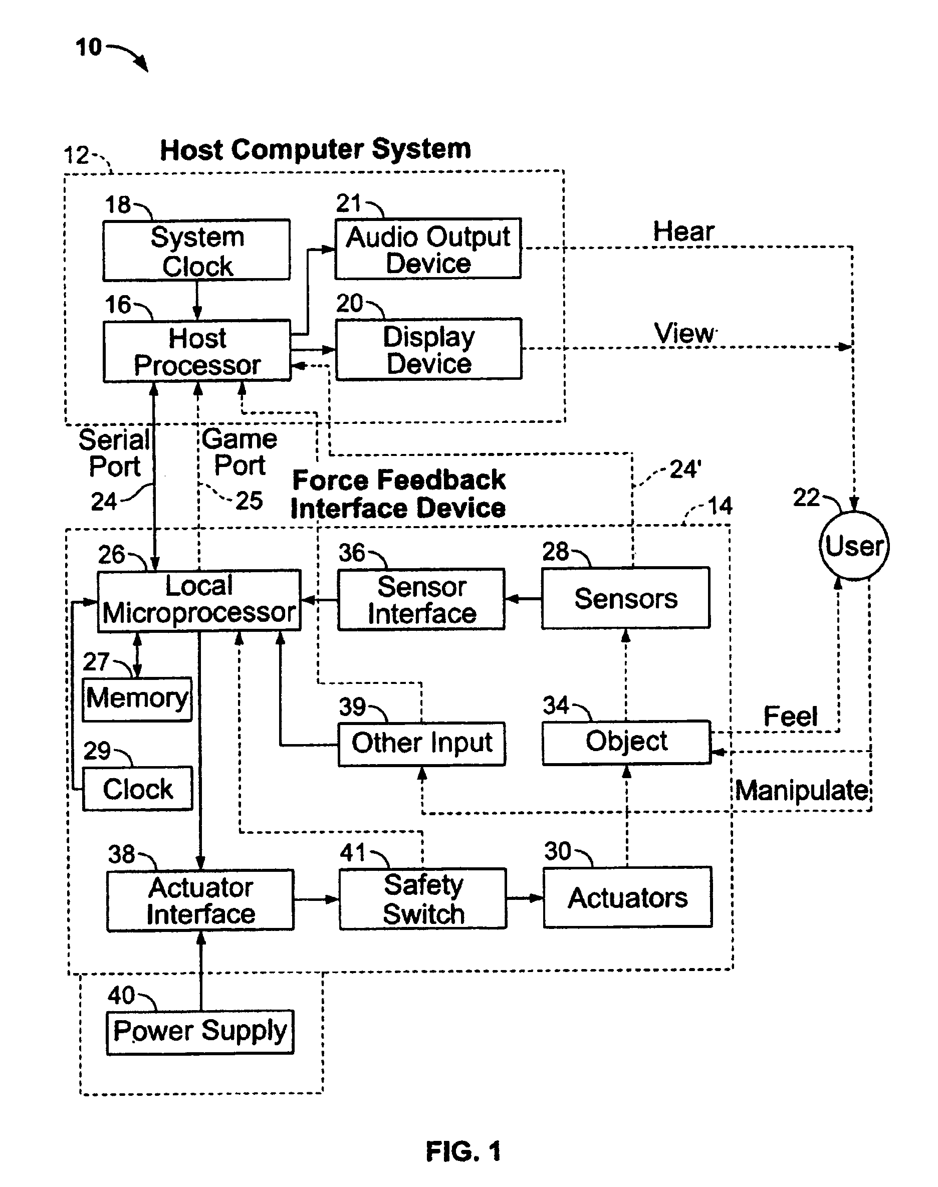
[0038]FIG. 1 is a block diagram illustrating a force feedback interface system 10 of the present invention controlled by a host computer system. Interface system 10 includes a host computer system 12 and an interface device 14.

[0039]Host computer system 12 is preferably a personal computer, such as an IBM-compatible or Macintosh personal computer, or a workstation, such as a SUN or Silicon Graphics workstation. For example, the host computer system can a personal computer which operates under the MS-DOS or Windows operating systems in conformance with an IBM PC AT standard. Alternatively, host computer system 12 can be one of a variety of home video game systems commonly connected to a television set, such as systems available from Nintendo, Sega, or Sony. In other embodiments, home computer system 12 can be a television “set top box” or a “network computer” which can be used, for example, to provide interactive computer functions to users over networks.

[0040]In the described embodi...


PUM


Abstract

A method and apparatus for providing dynamic force sensations for use with a force feedback interface device. A force feedback interface device is connected to a host computer that implements a graphical environment. The host sends commands and command parameters to the interface device to initiate and characterize dynamic force sensations output on a user manipulatable object, such as a joystick. The interface device can include a local microprocessor for implementing force sensations by controlling actuators and reading sensors according to the host commands. A dynamic force routine can control the dynamic force sensations by implementing a simulated physical system including a simulated mass capable of motion independent of the user object. The physical system provides forces on the user object influenced by motion of both the user object and the simulated mass.

Description

[0001]This is a Divisional application Ser. No. 08 / 846,011 filed Apr. 25, 1997, now U.S. Pat. No. 6,147,674 which is a continuation-in-part of application Ser. Nos. 08 / 566,282, now U.S. Pat. No. 5,734,373, filed Dec. 1, 1995, and Ser. No. 08 / 664,086, now U.S. Pat. No. 6,028,593, filed Jun. 14, 1996, the disclosures of which are incorporated herein by reference.BACKGROUND OF THE INVENTION[0002]The present invention relates generally to interface devices for allowing humans to interface with computer systems, and more particularly to computer interface devices that allow the user to provide input to computer systems and allow computer systems to provide force feedback to the user.[0003]Users interact with computer systems for a variety of reasons. A computer system typically displays a visual environment to a user on a display output device. Using an interface device, a user can interact with the displayed environment to perform functions and tasks on the computer, such as playing a g...

Claims


Application Information

Patent Timeline
IPC IPC(8): G09G5/00A63B24/00B25J9/16G05G9/047G06F3/00G06F3/01G06F3/038
CPCB25J9/1689G05G9/047G06F3/016G06F3/03543G06F3/038G06F3/0383A63B24/00A63F2300/1025A63F2300/1037G05G2009/04766H01H2003/008G06F2203/014G06F2203/015G05G2009/04777
Inventor ROSENBERG, LOUIS B.CHANG, DEAN C.
Owner IMMERSION CORPORATION
Why Eureka
Try Eureka