Gas-liquid separator and ejector refrigerant cycle using the same

a technology of gas-liquid separator and refrigerant cycle, which is applied in the direction of refrigeration components, transportation and packaging, lighting and heating equipment, etc., can solve the problems of increased production cost, increased weight and size of gas-liquid separator, etc., and achieve the effect of reducing weight and siz

Inactive Publication Date: 2006-05-09
DENSO CORP
View PDF8 Cites 12 Cited by
  • Summary
  • Abstract
  • Description
  • Claims
  • Application Information

AI Technical Summary

Benefits of technology

[0007]It is an object of the present invention to reduce the weight and the size of a gas-liquid separator for a refrigerant cycle, while gas-liquid separation performance of the gas-liquid separator can be improved.
[0009]In a gas-liquid separator for a refrigerant cycle with a compressor, a radiator, an evaporator and an ejector, a tank body is provided for separating refrigerant flowing from the ejector into gas refrigerant and liquid refrigerant. The tank body is disposed such that the gas refrigerant in the tank body is supplied to a suction side of the compressor and the liquid refrigerant in the tank body is supplied toward the evaporator. Further, the tank body has an equivalent inner diameter (D) that is set in a range of 2 cm–6 cm, and a ratio of a vertical dimension (H) of the tank body to the equivalent inner diameter (D) thereof is larger than 1. In the refrigerant cycle having the ejector for decompressing refrigerant from the radiator, even when refrigerant is super-heated in the evaporator, the super-heated gas refrigerant is heat-exchanged with liquid refrigerant in the ejector, and generally becomes saturated gas refrigerant in the ejector. Therefore, super-heated gas refrigerant from the evaporator can be prevented from flowing directly into the gas-liquid separator. Thus, boiling can be prevented from occurring in the gas-liquid separator due to evaporation of liquid refrigerant in the gas-liquid separator. Therefore, the vertical dimension H of the gas-liquid separator can be made larger than the equivalent inner diameter D thereof. That is, the ratio of the vertical dimension (H) of the tank body to the equivalent inner diameter (D) thereof can be set larger than 1. According to the present invention, because the equivalent inner diameter (D) of the tank body is set in the range of 2 cm–6 cm, the gas-liquid separation performance can be improved while the weight and the size of the gas-liquid separator can be effectively reduced. For example, the tank body substantially has a cylindrical shape.

Problems solved by technology

Accordingly, the weight and the size of the gas-liquid separator increase, and its production cost also increases.

Method used


Image

  • Gas-liquid separator and ejector refrigerant cycle using the same
  • Gas-liquid separator and ejector refrigerant cycle using the same
  • Gas-liquid separator and ejector refrigerant cycle using the same

Examples


first embodiment

(First Embodiment)

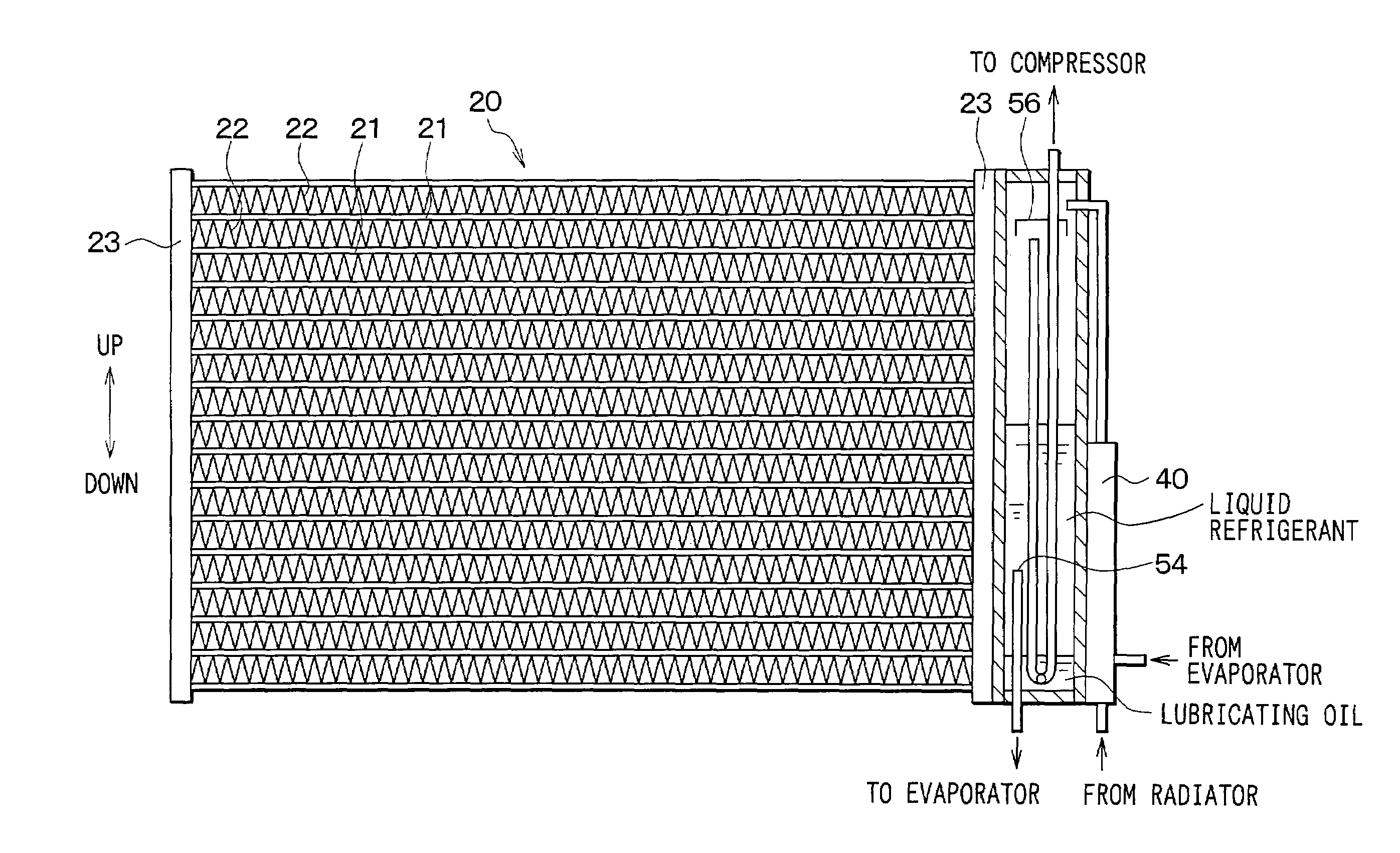
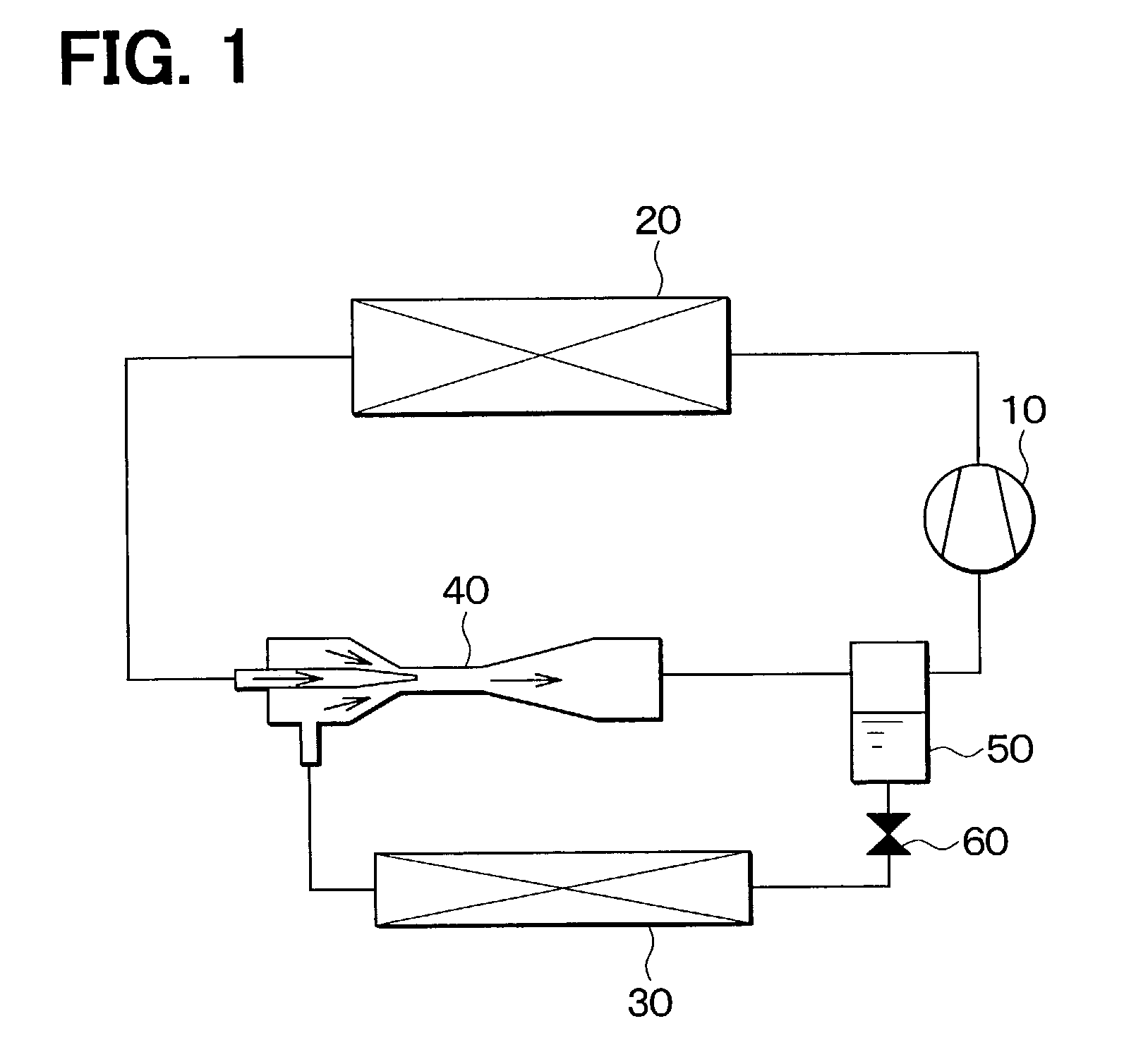
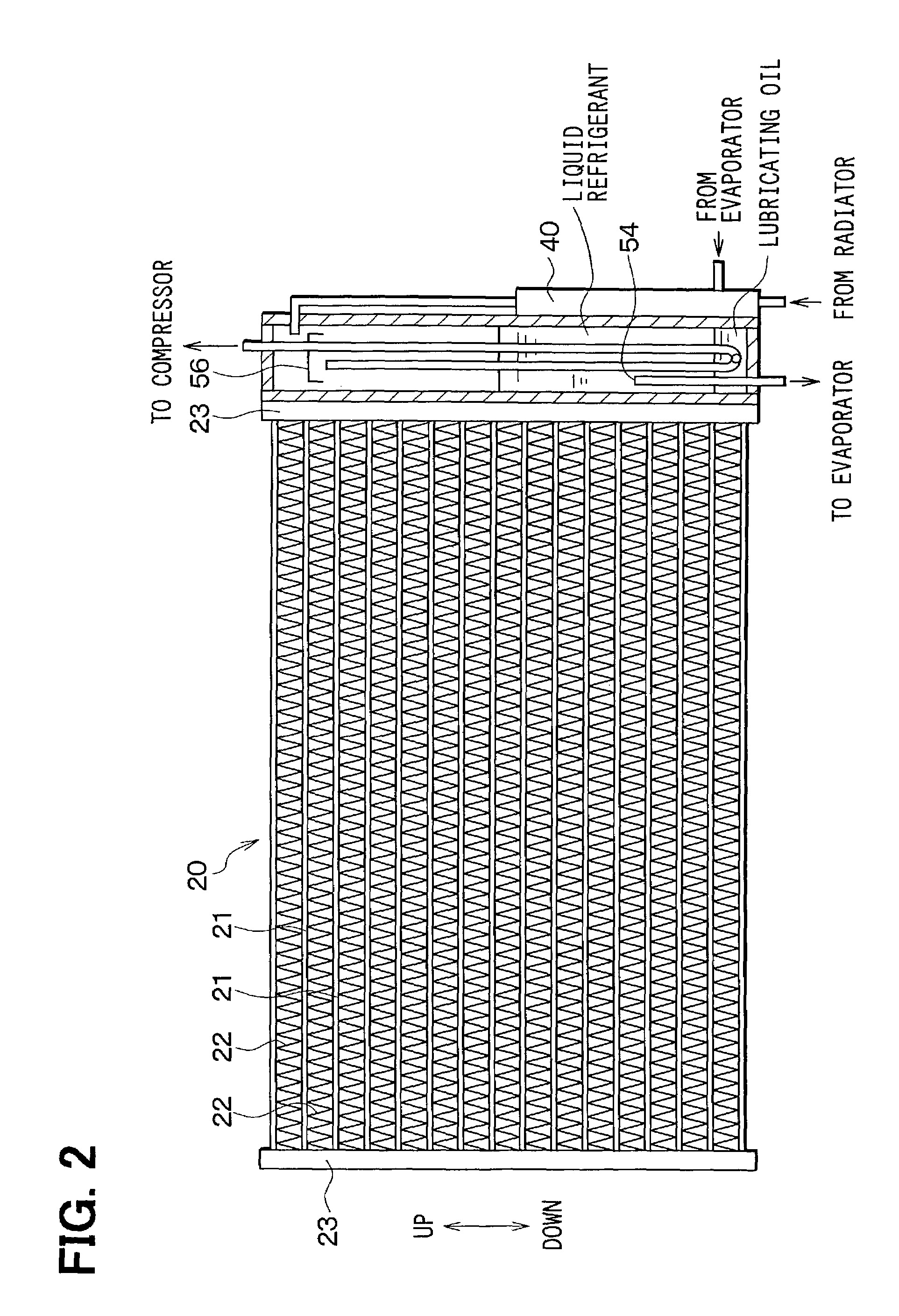
[0024]In the first embodiment, as shown in FIG. 1, an ejector refrigerant cycle of the present invention is typically used for a vehicle air conditioner. A compressor 10 is a variable displacement compressor for sucking and compressing refrigerant by using motive power from a vehicle engine. A radiator 20 is a high-pressure heat exchanger, and radiates heat of refrigerant by performing heat exchange between outside air and refrigerant discharged from the compressor 10. In the first embodiment, although carbon dioxide is typically used as the refrigerant, fleon (e.g., R404, R134a) can be used as the refrigerant. When fleon is used as the refrigerant, refrigerant is condensed in the radiator 20. However, when carbon dioxide is used as the refrigerant, refrigerant pressure at a high pressure side is equal to or higher than the critical pressure of the refrigerant. Therefore, when carbon dioxide is used as the refrigerant, the refrigerant is not condensed in the radiat...

second embodiment

(Second Embodiment)

[0043]In the second embodiment, as shown in FIGS. 6A, 6B, a container for containing the ejector 40 is molded integrally with the tank body 51 by extrusion or drawing, so that at least a part of the ejector 40 is integrated to the gas-liquid separator 50. In the second embodiment, the nozzle, the mixing portion and the diffuser of the ejector 40 are arranged in a direction parallel to the longitudinal direction of the tank body 51. Therefore, the gas-liquid separator 50 and the ejector 40 can be readily integrated to each other. In the second embodiment, the other parts are similar to those of the above-described first embodiment, and the advantage described in the first embodiment can be obtained.

third embodiment

(Third Embodiment)

[0044]The third embodiment is a modification of the second embodiment. As shown in FIGS. 7A, 7B, pipes for connecting the ejector 40 and the gas-liquid separator 50 or a part of the container for containing the ejector are molded integrally with the tank body 51 by extrusion or drawing, so that at least a part of the ejector 40 is integrated to the gas-liquid separator 50. In the third embodiment, the other parts are similar to those of the above-described second embodiment.


PUM


Abstract

In an ejector refrigerant cycle, even if refrigerant is super-heated in an evaporator, super-heated gas refrigerant does not directly flow into a gas-liquid separator, so that boiling of refrigerant does not occur in the gas-liquid separator due to evaporation of refrigerant in the gas-liquid separator. When an equivalent inner diameter (D) of a tank body of the gas-liquid separator is set in a range of 2 cm–6 cm, and when a ratio of a vertical dimension (H) of the tank body to the equivalent inner diameter (D) thereof is larger than 1, a wall thickness of the tank body can be reduced while gas-liquid separation performance in the gas-liquid separator can be improved.

Description

CROSS-REFERENCE TO RELATED APPLICATION[0001]This application is related to and claims priority from Japanese Patent Application No. 2002-136953 filed on May 13, 2002, the content of which is hereby incorporated by reference.BACKGROUND OF THE INVENTION[0002]1. Field of the Invention[0003]The present invention relates to a gas-liquid separator and an ejector refrigerant cycle using the gas-liquid separator. The gas-liquid separator can be suitably used for a vapor-compression refrigerant cycle system.[0004]2. Description of Related Art[0005]In a vapor-compression refrigerant cycle system, a gas-liquid separator for storing excess refrigerant is provided at a high pressure side or a low pressure side so as to compensate thermal-load variation. The gas-liquid separator separates refrigerant into gas refrigerant and liquid refrigerant. Specifically, when the gas-liquid separator is provided at the low pressure side, the gas refrigerant in the gas-liquid separator is supplied to a suction...

Claims


Application Information

Patent Timeline
Patent Type & Authority Patents(United States)
IPC IPC(8): F25B1/06F25B43/00F25B1/00B60H1/32F25B9/00F25B39/04F25B41/00
CPCF25B41/00B60H2001/3297F25B9/008F25B39/04F25B2500/18F25B2341/0012F25B2400/23F25B2500/01F25B2309/061
Inventor NISHIDA, SHINTOMATSU, YOSHITAKAKITAMURA, KEIICHI
Owner DENSO CORP
Why Eureka
Try Eureka