Projector and image projection system

a projector and projection system technology, applied in the field of projectors, can solve the problems of shortening the life of the discharge lamp, inconvenient operation for operators, waste,

Inactive Publication Date: 2006-05-09
CANON KK
View PDF4 Cites 28 Cited by
  • Summary
  • Abstract
  • Description
  • Claims
  • Application Information

AI Technical Summary

Benefits of technology

[0011]In one aspect of the present invention, the image projector includes a discharge lamp, an image projector unit for displaying an image on a screen by emitting light from the discharge lamp, a cooling fan for reducing the temperature of the discharge lamp or the image projector unit, and a cooling fan controller for controlling the rotation speed of the cooling fan, wherein the controller controls the cooling fan to stop the rotation in the standby mode. In another aspect of the present invention, the image projector controls the rotation speed of the cooling fan based on detected temperature of the discharge lamp or the image projector unit. The image projector includes a sensor for detecting a detected temperature of the discharge lamp and / or the image projector unit. In one embodiment, the controller controls the cooling fan to incrementally reduce the rotational speed until the cooling fan completely stops responsive to the detected temperature being not lower than a lower temperature limit. In another embodiment, the controller controls the fan to incrementally increase the rotation speed responsive to the detected temperature being higher than an upper temperature limit; otherwise, the controller controls the fan to incrementally decrease the rotation speed.

Problems solved by technology

This waiting time causes inconvenience to the operator.
Moreover, when the projector is not required to project images (i.e., when the projector is in standby mode), maintaining the supply of electric power to the discharge lamp at the same level as in a normal mode in order to maintain the discharge state of the discharge lamp so that the discharge lamp continues to be lit is not only wasteful but also shortens the lifespan of the discharge lamp.
Once the temperature exceeds a predetermined temperature, the lifetime and performance of the discharge lamp and the optic system become degraded.
When the cooling fan is rotating, it generates noise.
The noise of the cooling fan is particularly disturbing if the cooling fan keeps rotating when the projector is switched from the normal mode to the standby mode to have a discussion during a presentation.

Method used


Image

  • Projector and image projection system
  • Projector and image projection system
  • Projector and image projection system

Examples


first embodiment

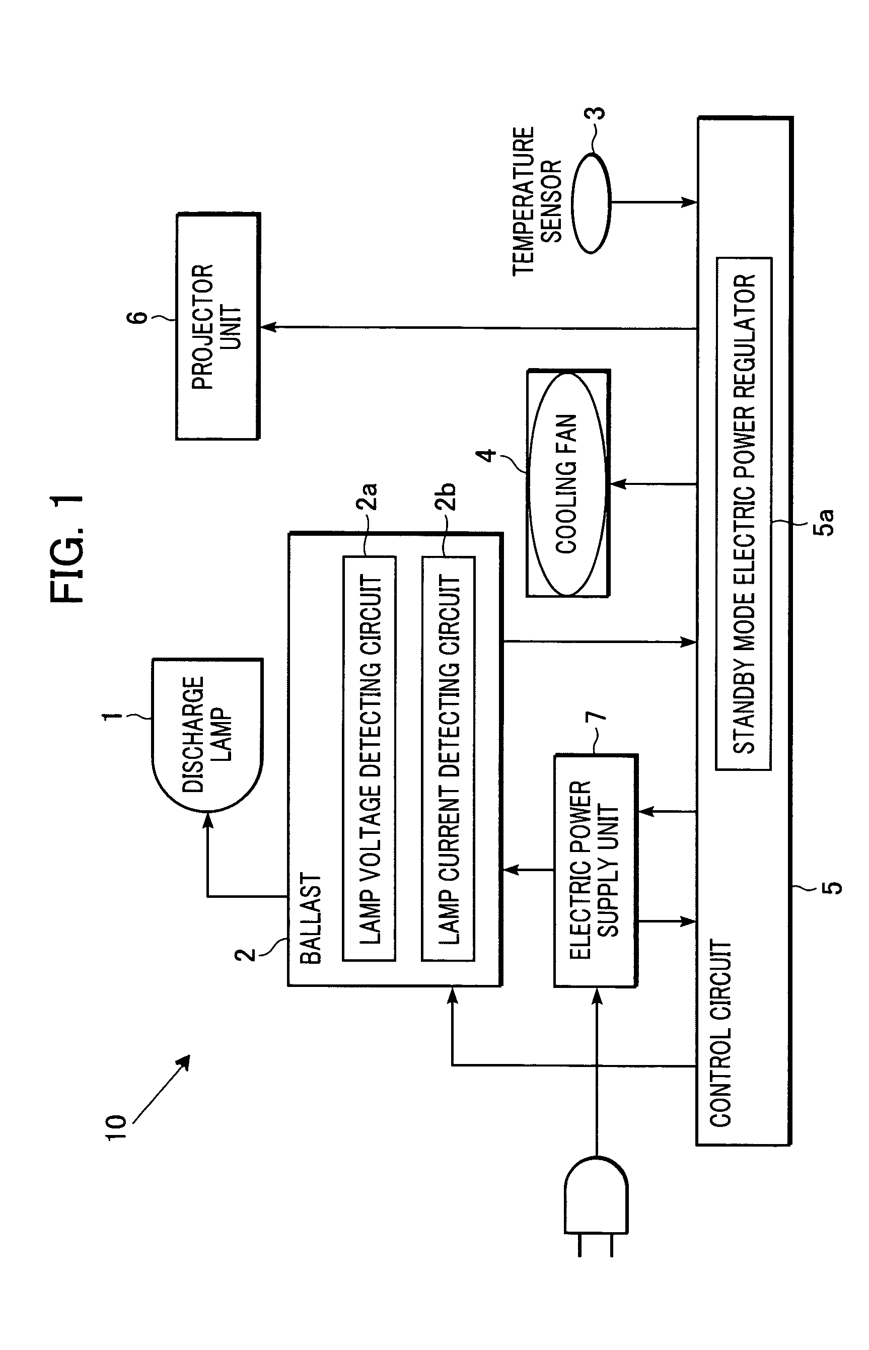
[0018]FIG. 1 is a block diagram illustrating an image projector 10 according to one embodiment of the present invention.

[0019]A discharge lamp 1 is used as a light source of the image projector 10. A ballast 2 regulates electric power supplied to the discharge lamp 1 and controls the lighting of the discharge lamp 1. The ballast 2 includes a lamp voltage detecting circuit 2a for detecting lamp voltage during lighting of the discharge lamp 1, and a lamp current detecting circuit 2b for detecting lamp current during lighting of the discharge lamp 1. A temperature sensor 3 detects the temperature of the discharge lamp 1 and / or in the vicinity of the discharge lamp 1. A cooling fan 4 reduces the temperature of the discharge lamp 1 and / or in the vicinity of the discharge lamp 1.

[0020]A projector unit 6 projects an image onto a screen (not shown in the drawing) by emitting light in accordance with image signals sent from a control circuit 5. An electric power supply unit 7 generates elect...

second embodiment

[0035]A second embodiment of the present invention is a variation of the above-mentioned first embodiment. In the first embodiment, the minimum electric power Pmin required to keep the discharge lamp 1 lit was a known predetermined value experimentally obtained. In step S203, the amount of electric power supplied to the discharge lamp 1 was controlled by setting Pmin as a target. In this second embodiment, however, the minimum electric power Pmin required to keep the discharge lamp 1 lit is not known. Instead, the electric power supplied to the discharge lamp 1 is controlled based on the temperature detected by the temperature sensor 3.

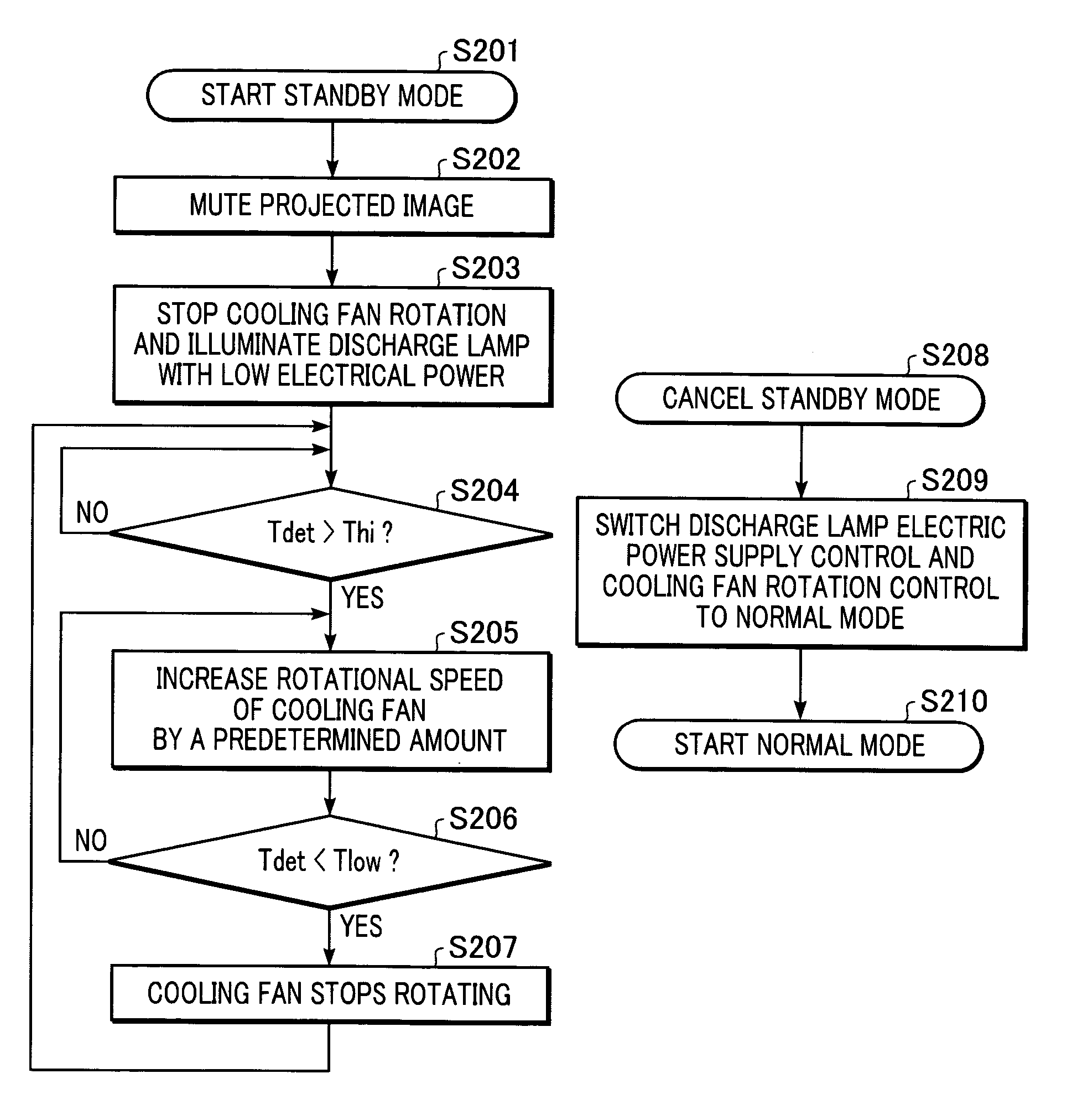
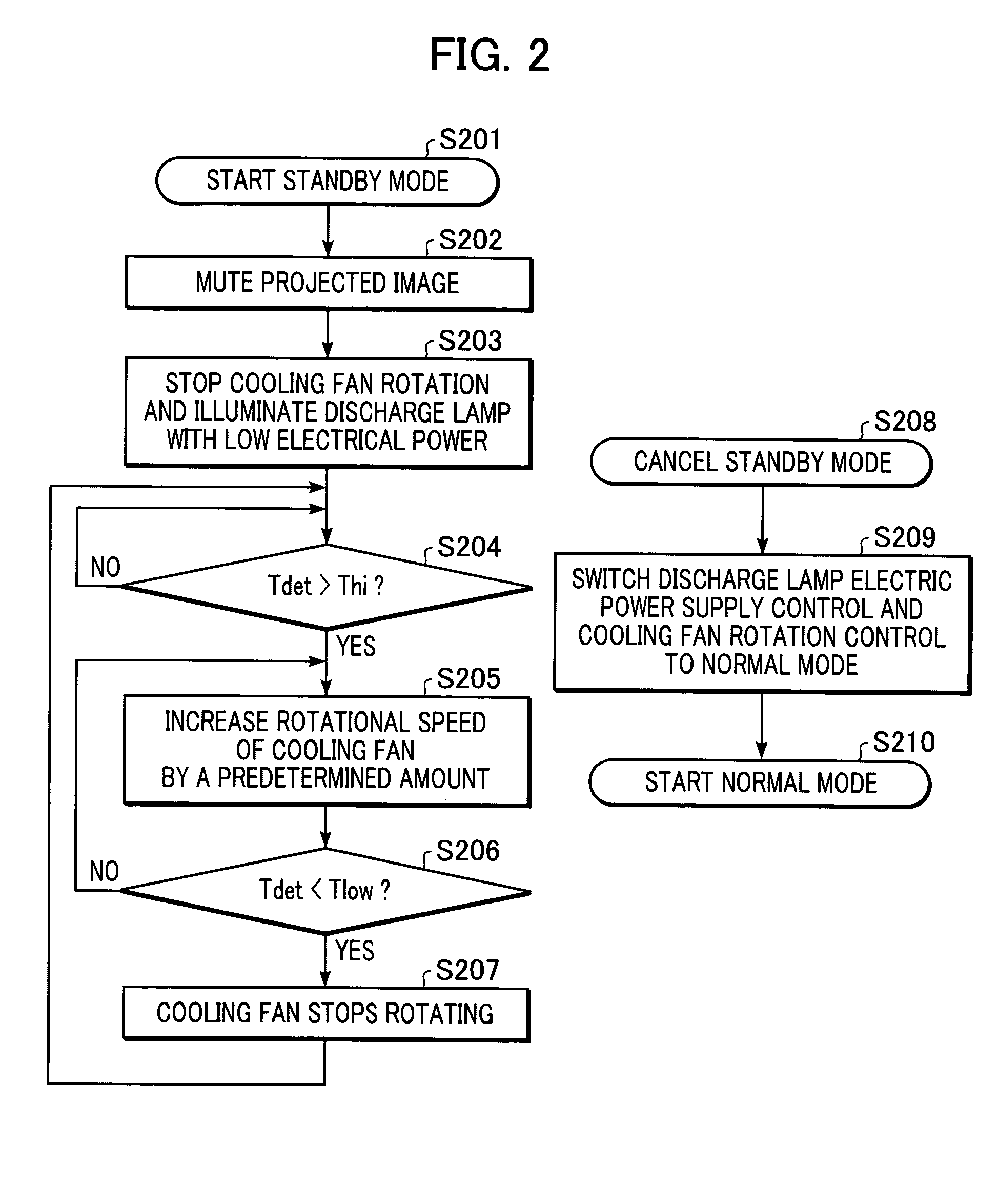
[0036]The operation of the image projector 10 in standby mode according to the second embodiment of the present invention is described below by referring to the flow chart in FIG. 3. FIG. 3 is a flow chart describing the operation of a standby mode according to the second embodiment of the present invention.

[0037]The processes of starting the standby ...

third embodiment

[0041]A third embodiment of the present invention is also a variation of the first embodiment. In the first embodiment, the electric power supplied to the discharge lamp 1 is reduced rapidly by setting the minimum amount of electric power Pmin as a target, wherein Pmin is the electric power required to keep the discharge lamp 1 lit and is a value known from step S204. In the third embodiment, however, a margin is set for the minimum amount of electric power Pmin required to keep the discharge lamp lit. The electric power supplied to the discharge lamp 1 is reduced stepwise / incrementally by taking this margin into consideration.

[0042]The operation of the projector in standby mode according to the third embodiment of the present invention is described below by referring to the flow chart in FIG. 4. FIG. 4 is a flow chart describing the operation of a standby mode according to a third embodiment of the present invention.

[0043]The processes of starting the standby mode and turning off t...


PUM


Abstract

An image projector comprises a discharge lamp, image projecting means for displaying an image on a screen by emitting light from the discharge lamp, electric power regulating means for regulating the electric power supplied to the discharge lamp, a cooling fan for reducing the temperature of the discharge lamp or the image projecting means, a cooling fan controlling means for controlling the rotation of the cooling fan, and a sensor for detecting a temperature of the discharge lamp or the image projecting means, wherein the rotation of the cooling fan is stopped when the image projector is in a standby mode. In the standby mode, the cooling fan controlling means controls the rotation speed of the cooling fan based on the detected temperature.

Description

BACKGROUND OF THE INVENTION[0001]1. Field of the Invention[0002]The present invention relates to a projector such as a liquid crystal projector for displaying images formed by light emitted from a discharge lamp onto a screen. More specifically, the invention relates to the control of the rotation of a cooling fan in a standby mode in which images are not projected on the screen.[0003]2. Description of the Related Art[0004]A known discharge lamp used as a light source of a projector cannot be turned on immediately after it is turned off. The discharge lamp can only be turned on again one to one and a half minutes after the discharge lamp has been turned off when the temperature of the discharge lamp is sufficiently reduced. When a projector is used in a presentation during a meeting, it might be turned off for a short period of time during a discussion not requiring an image to be projected. Once the discharge lamp is turned off, it cannot be turned immediately back on again to proj...

Claims


Application Information

Patent Timeline
Patent Type & Authority Patents(United States)
IPC IPC(8): G03B21/16F21V29/00F21V7/20G03B21/18G03B21/20H04N5/74F21S2/00F21V29/02F21V29/505F21Y101/00G03B21/00G03B21/14G03B21/26H04N5/63
CPCG03B21/16H04N5/74H04N5/63H04N9/3141H04N5/7441
Inventor YASUDA, HITOSHI
Owner CANON KK
Why Eureka
Try Eureka