Microrobot for surgical applications

a microrobot and surgical technology, applied in the field of microrobots, can solve problems such as response delay and leakage of electric curren

Inactive Publication Date: 2006-05-09
BOARD OF RGT UNIV OF NEBRASKA
View PDF51 Cites 175 Cited by
  • Summary
  • Abstract
  • Description
  • Claims
  • Application Information

AI Technical Summary

Problems solved by technology

A shape memory alloy (SMA) actuator has been proposed as well, but has some disadvantages, such as cooling, leaking electric current, and response delay (Fukuda et al., Proceedings of the 1994 IEEE International Conference on Robotics and Automation, p.

Method used


Image

  • Microrobot for surgical applications
  • Microrobot for surgical applications
  • Microrobot for surgical applications

Examples


example 1

Mobile Mini Robot

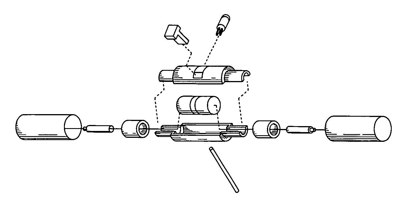
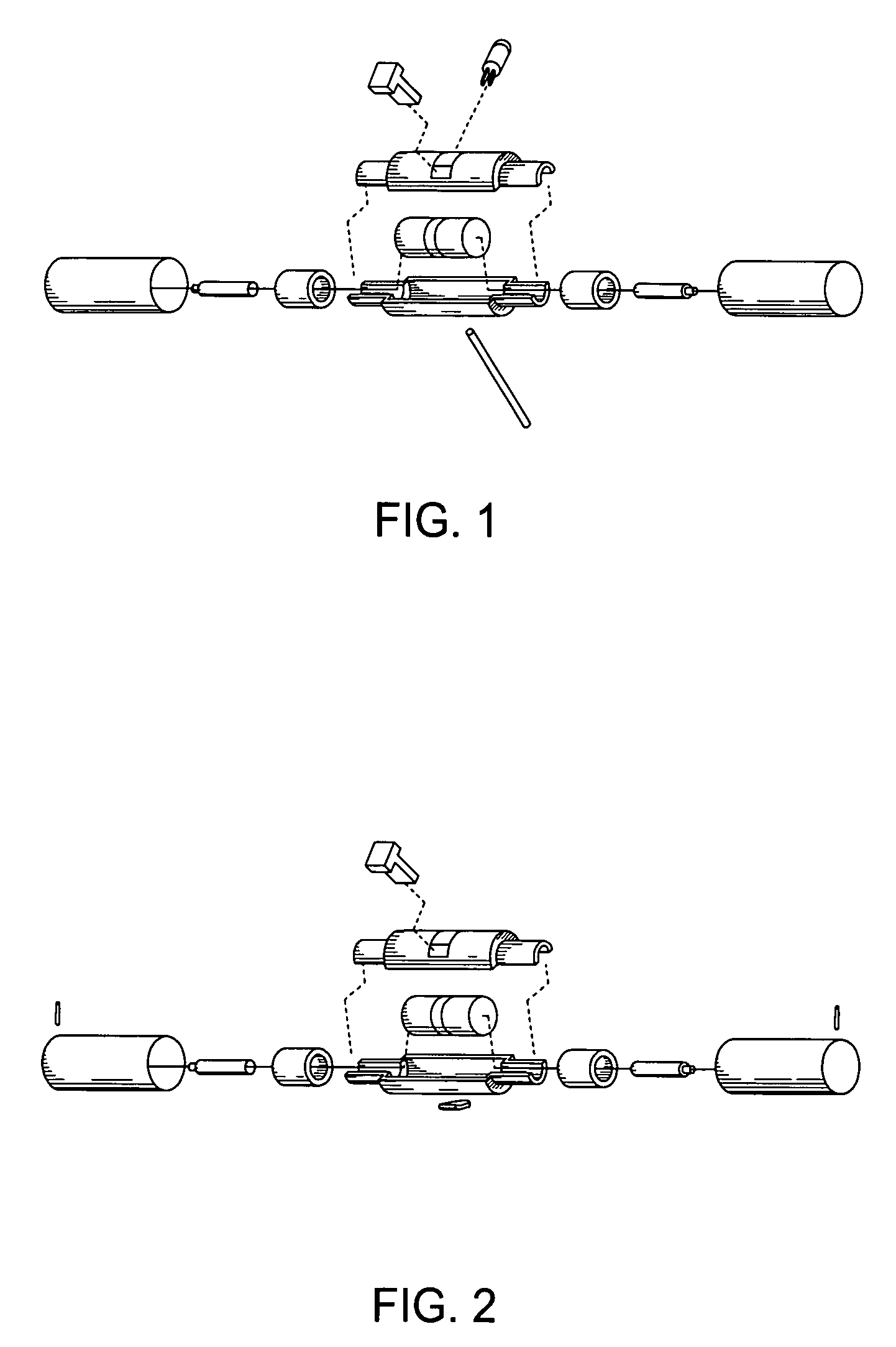
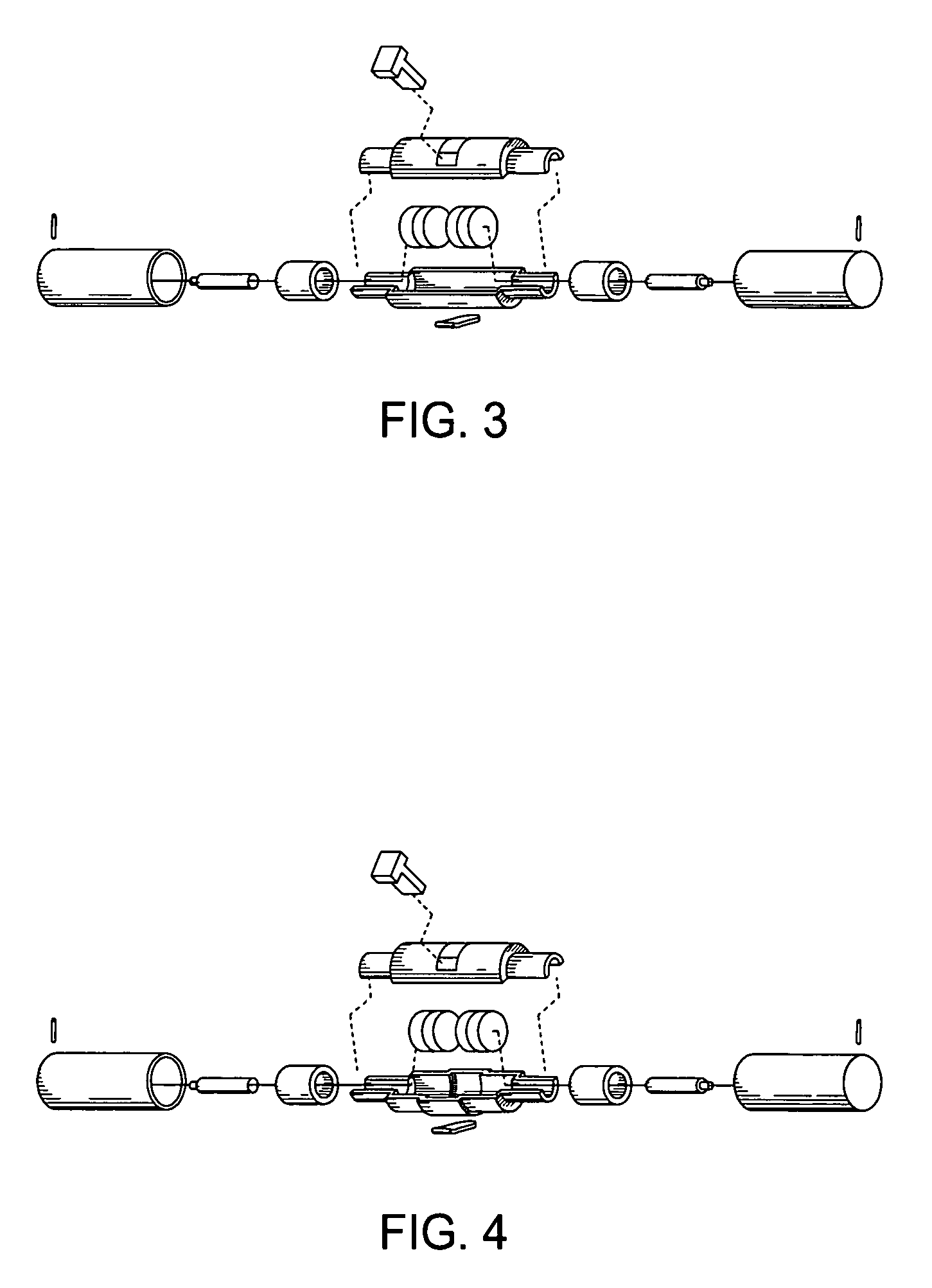
[0065]The constraints placed on the size of the micro-robot according to the present invention were factors in determining the size and shape of the initial prototype of the embodiment described herein. The mobile robot was constructed to be cylindrical in shape, with the wheels of the mobile robot covering most of the body. The robot's diameter was designed to be less than 15 mm so as to be able to, in this embodiment, fit through a port in a tool that is currently used in laparoscopic surgical techniques.

[0066]The size and function of this robot dictated also the use of very small electric motors. The first motors tested were motors that are used to vibrate pagers and mobile phones; however, these motors were found to be inadequate to supply the torque needed to move the robot. A suitable motor was selected. The electronics selected initially consisted of a modified control chip for the brushless motors that were selected. After control for the motors was establis...

example 2

Manipulator Arm Design

[0118]The design process of the manipulator arm involved a lengthy trial and error process that eventually resulted in a working prototype. The original design was hand-sketched on paper, then turned into a three-dimensional (3D) computer-aided-drafting (CAD) file using Solid Works 2001. Utilizing the CAD program, the linkages, motors and camera were drawn with accurate dimensions.

[0119]The initial designs for one embodiment of the invention included the idea of conserving space by attaching motors to the linkages. Using miter gears, the rotational force of the motors was transmitted 90 degrees to rotate each link. The CAD drawing shown in FIG. 8 illustrates the initial design with all pieces drawn to scale. The CAD design was a big step in determining the lengths of each linkage and how the size of each component would relate to one another. The miter gears are a stock product from Stock Drive Products / Sterling Instruments. The initial CAD design allowed deter...


PUM


Abstract

The present invention provides a micro-robot for use inside the body during minimally-invasive surgery. The micro-robot may include various sensors, imaging devices or manipulators.

Description

BACKGROUND OF THE INVENTION[0001]Interest in micro-robotics has increased rapidly in recent years. This is due mainly to technology development in the fields of microelectronics, micromachining, and microactuation. Currently, it is possible to build and test miniature systems that include numerous features, including sensors, actuators, and embedded control subsystems. The trend toward miniaturization is seen not only in industrial applications, but in medical applications as well.[0002]There are many industrial applications for micro-robots. Micro-robots are suitable for work in small and inaccessible places; for example, in dismantling and reassembling factory pipelines, inspection of small environments, measuring various parameters, miniature manipulation, repairs, micromachining, complex molecular and atomic operations, and precision tooling, grasping, transport, and positioning with nanoscale motion resolution. Micro-robots that mimic insects have been developed, though current...

Claims


Application Information

Patent Timeline
Patent Type & Authority Patents(United States)
IPC IPC(8): B25J5/00A61B19/00B25J7/00
CPCA61B1/041A61B5/05A61B5/416A61B19/22B08B9/045B25J5/00B25J7/00B25J9/065Y10T74/20317A61B2019/2249A61B34/70A61B34/72B33Y80/00
Inventor OLEYNIKOV, DMITRYFARRITOR, SHANEHADZIALIC, ADNANPLATT, STEPHEN R.
Owner BOARD OF RGT UNIV OF NEBRASKA
Why Eureka
Try Eureka