Insulated glass assembly with an internal lighting system

a technology of lighting system and insulated glass, which is applied in the direction of fixed installation, lighting and heating apparatus, instruments, etc., can solve the problems of inability to incorporate internal lighting system into ig assembly, inability to meet the needs of ig assembly use, and relatively short life span of even the best incandescent lamp, so as to achieve the effect of improving safety features and reducing thermal energy

Inactive Publication Date: 2006-05-16
TEM PACE LLC
View PDF30 Cites 36 Cited by
  • Summary
  • Abstract
  • Description
  • Claims
  • Application Information

AI Technical Summary

Benefits of technology

[0005]This invention provides an internally illuminated insulated glass assembly for use in window or door applications. The IG assembly of this invention uses an internal lighting system of light emitting diodes (LEDs). The LED light systems provide dependable illumination but emit relatively little thermal energy. Consequently, the LED light system maintains the thermal insula...

Problems solved by technology

Attempts, however, to incorporate internal lighting systems into IG assemblies have been unsuccessful and impractical.
Conventional incandescent lights are ill suited for use in IG assemblies for a variety of reasons.
One obvious problem is the relatively short life span of even the best incandescent lamp.
Once a lamp filament burns out, the entire glass unit must be replaced, which makes such IG assemblies cost prohibitive.
A more subtle, but equally significant problem is the thermal energy emitted from the conventional incandescent lights.
Th...

Method used


Image

  • Insulated glass assembly with an internal lighting system
  • Insulated glass assembly with an internal lighting system
  • Insulated glass assembly with an internal lighting system

Examples


Embodiment Construction

[0020]The preferred embodiments herein described are not intended to be exhaustive or to limit the invention to the precise form disclosed. They are chosen and described to explain the invention so that others skilled in the art might utilize its teachings.

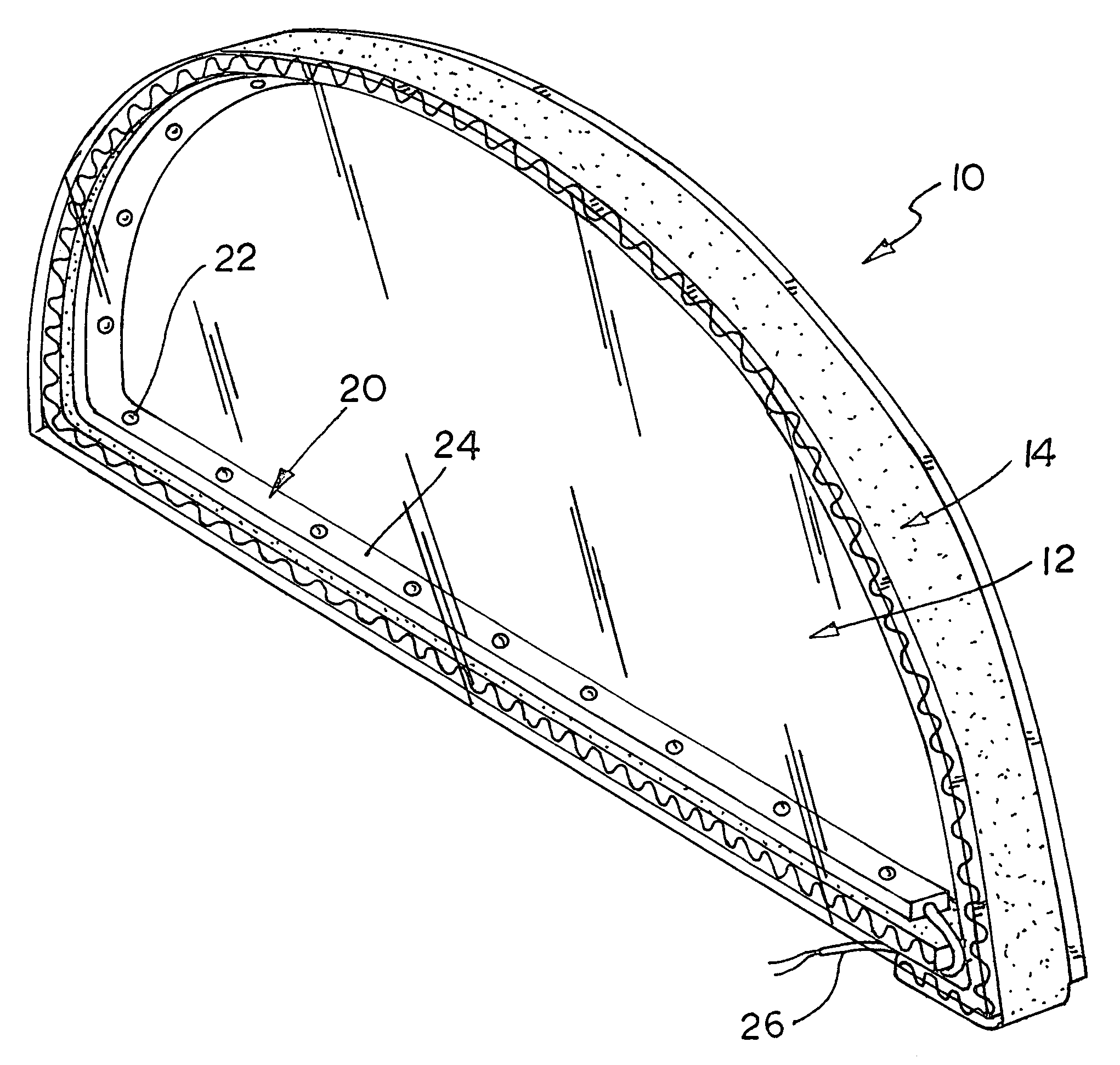
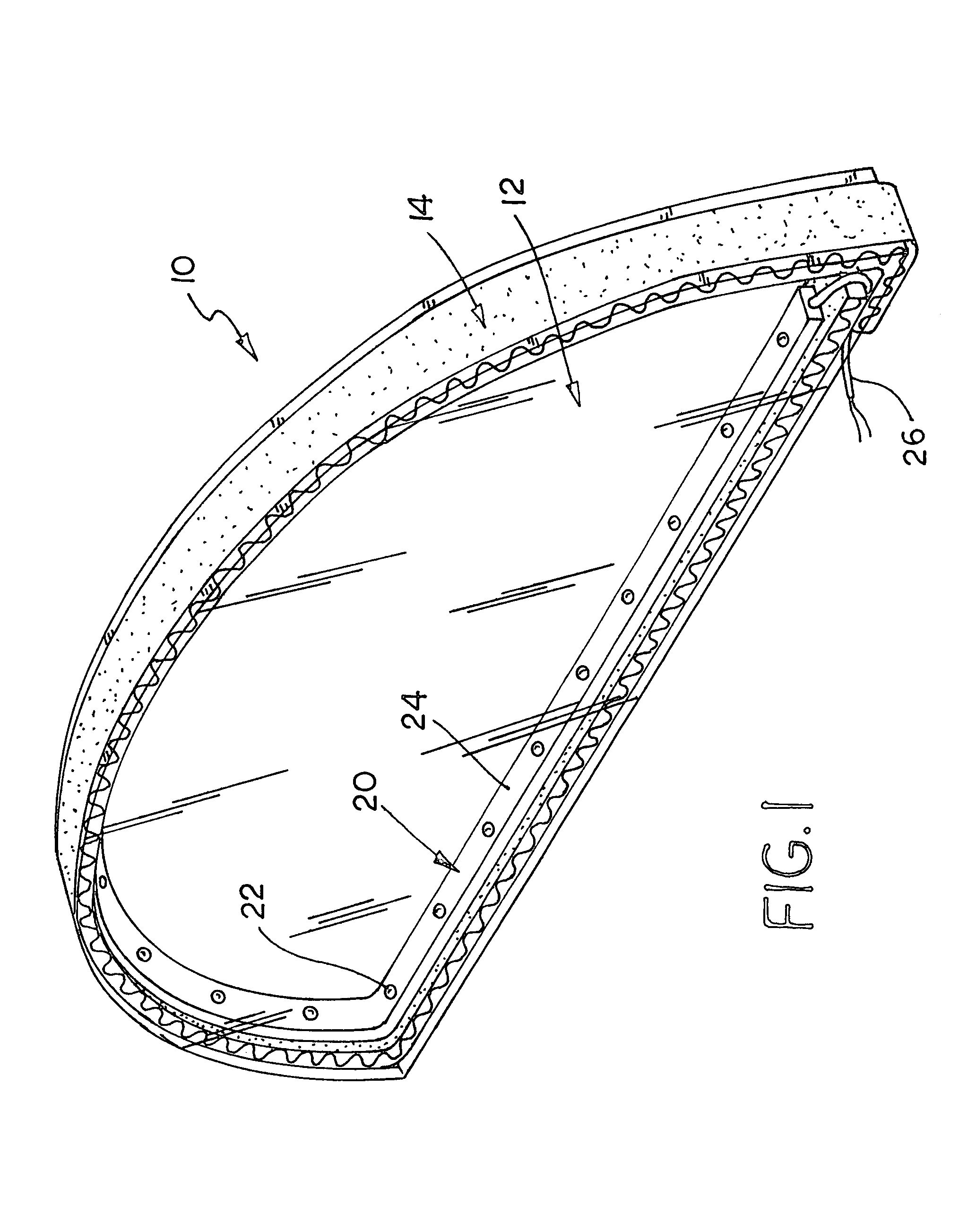
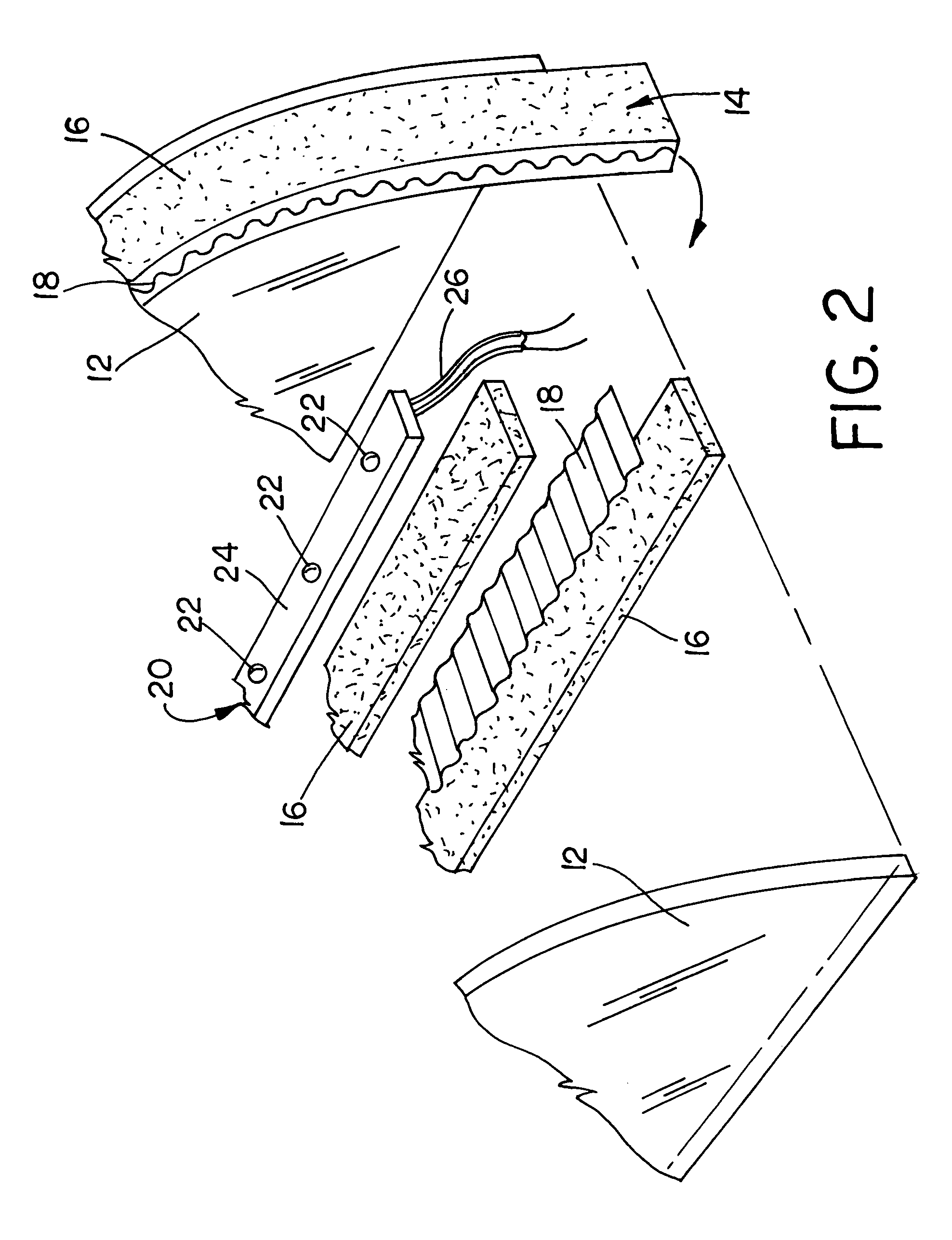
[0021]FIGS. 1–3 illustrate the basic design and construction of the insulated glass assembly of this invention, which is designated as reference numeral 10. IG assembly 10 of FIGS. 1–3 is illustrated for use as a top lite window, but may be configured for use in any window or door application. FIGS. 4 and 5 illustrate other such window applications. FIG. 4 illustrates IG assembly 10 used in a top lite window for a doorway. FIG. 5 illustrates a second embodiment of IG assembly (a rectangular unit designated as reference numeral 10′) used in a side lite window for a doorway. Both embodiments have identical construction and differ only in the configuration of the glass panes. The embodiments illustrated and described herein are inten...


PUM


Abstract

An insulated glass (IG) assembly for windows which includes an internal lighting system is disclosed. The IG assembly includes two or more panes of glass, a spacer and a strip of light emitting diodes (LEDs). The spacer separates glass panes and provides the hermetic seal for the IG assembly. The spacer extends around the periphery of the glass panes with a portion of its ends overlapping to form a sealed corner joint. The LED light strip includes a plurality of LED lamps connected in series by thin electrical contact wires fixed in a flexible nonconductive substrate. The LED strip is fixed to the spacer and extends around the periphery of the insulated glass unit. The lead wires from the LED light strip pass through the corner joint between the overlapped ends of the spacer. The LED light systems provide dependable illumination but emit relatively little thermal energy. Consequently, the LED light system maintains the thermal insulating properties of an insulated glass unit. The IG assembly can be incorporated into top and side lite windows or incorporated directly into doors themselves.

Description

[0001]This invention relates to insulated glass panes used for windows, and describes an internally illuminated insulated glass pane.BACKGROUND OF INVENTION[0002]Insulated glass (IG) assemblies are used in most window and door applications. IG assemblies are constructed of two or more sheets (panes) of glass, and a spacer including a stabilizer and sealant strip placed between the sheets and extending around the entire perimeter of the panes. The separated glass panes create an envelop of dead air which when used in a window or door, greatly reduces the passage of heat through the pane.[0003]It has long been desirable to incorporate lighting systems into IG assemblies. Internally illuminating IG assemblies could replace exterior light systems in front of windows and doors with more aesthetically pleasing and unobtrusive internal lighting systems. Internally illuminated IG assemblies provide illumination on both sides of a window or doorway, which adds an important safety feature to ...

Claims


Application Information

Patent Timeline
IPC IPC(8): F21S8/00F21V1/00E06B1/00E06B3/66E06B7/28F21V33/00
CPCE06B3/66E06B7/28E06B1/006F21Y2101/02F21V33/006F21Y2115/10F21V27/02
Inventor KRAUSE, SR., RICHARD J.KRAUSE, JR., RICHARD J.
Owner TEM PACE LLC
Why Eureka
Try Eureka