

Humidity controlling apparatus
a humidity control and apparatus technology, applied in the direction of heating types, other chemical processes, separation processes, etc., can solve the problems of excessive room temperature and large electrical consumption, and achieve the effect of efficiently controlling humidity and small thermal energy
- Summary
- Abstract
- Description
- Claims
- Application Information
AI Technical Summary
Benefits of technology
Problems solved by technology
Method used
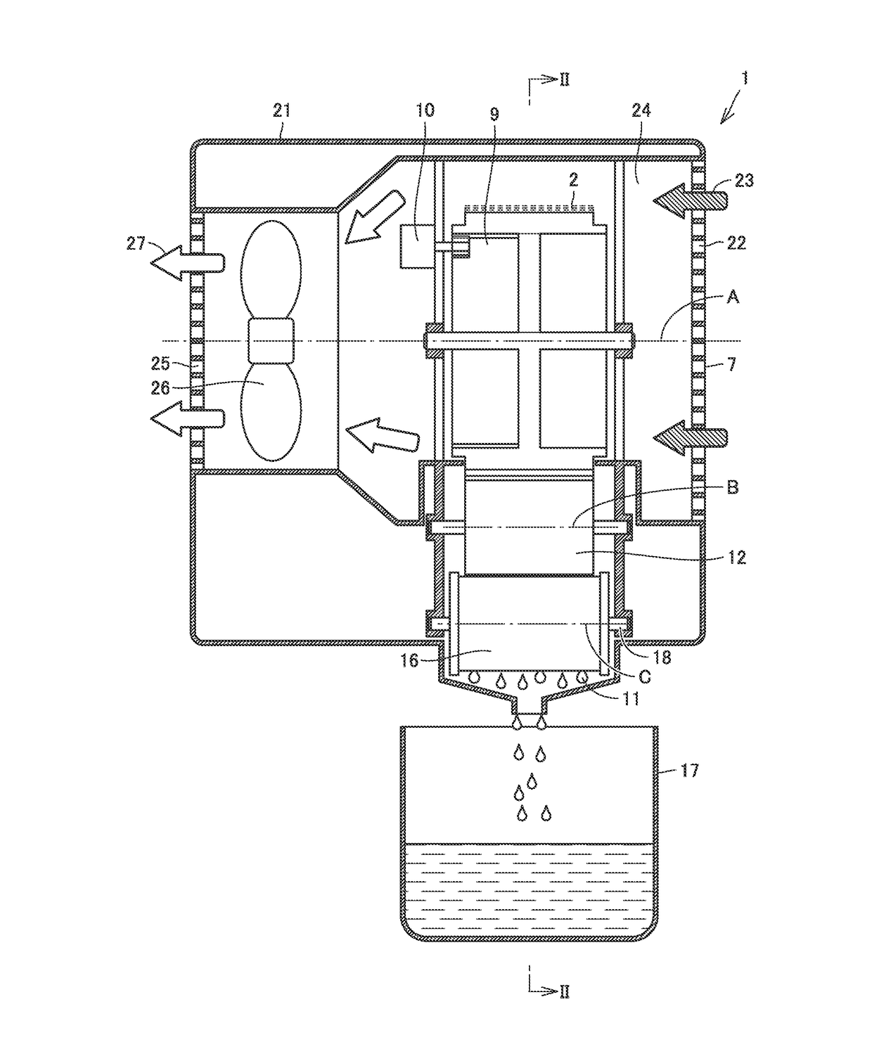
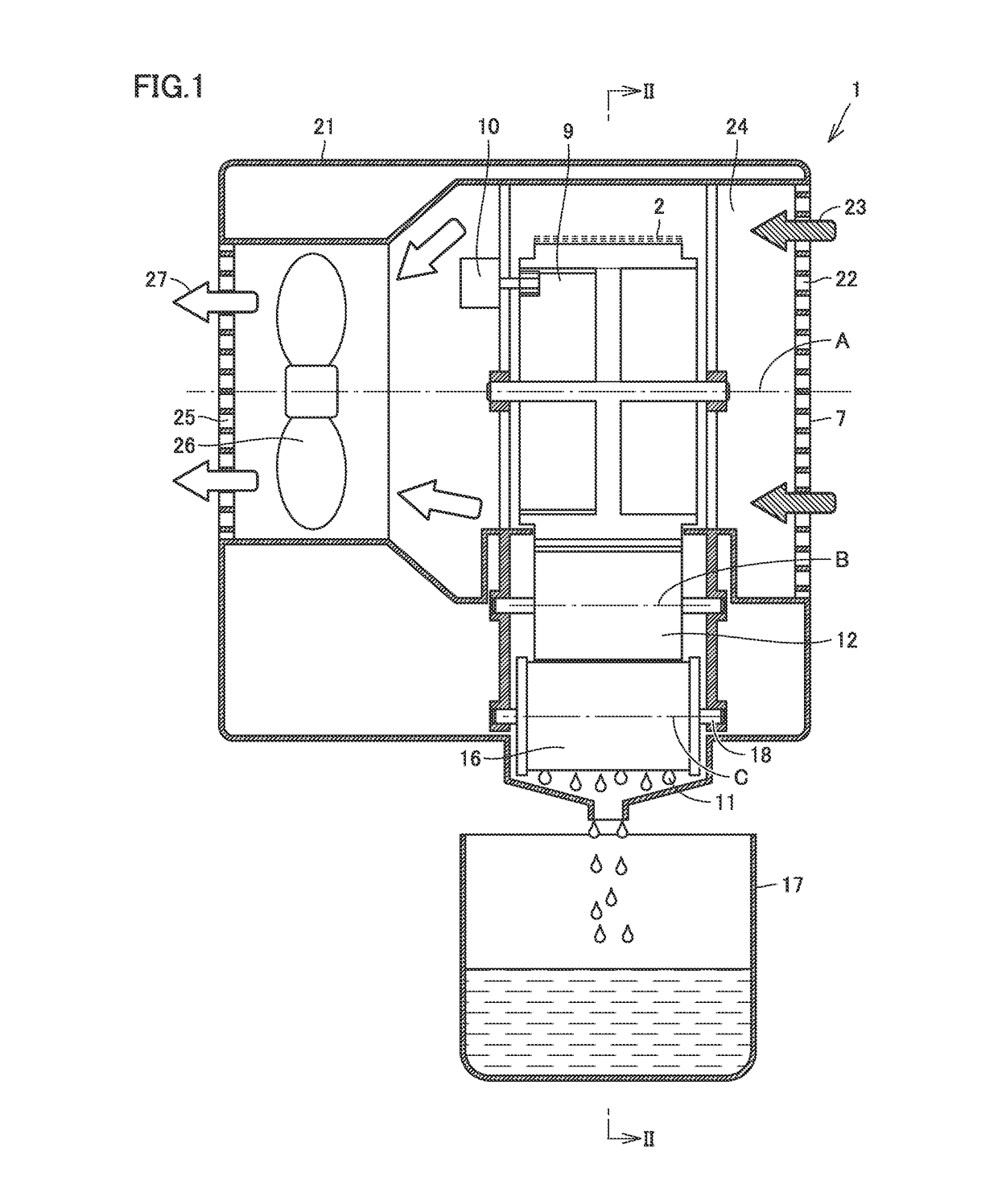
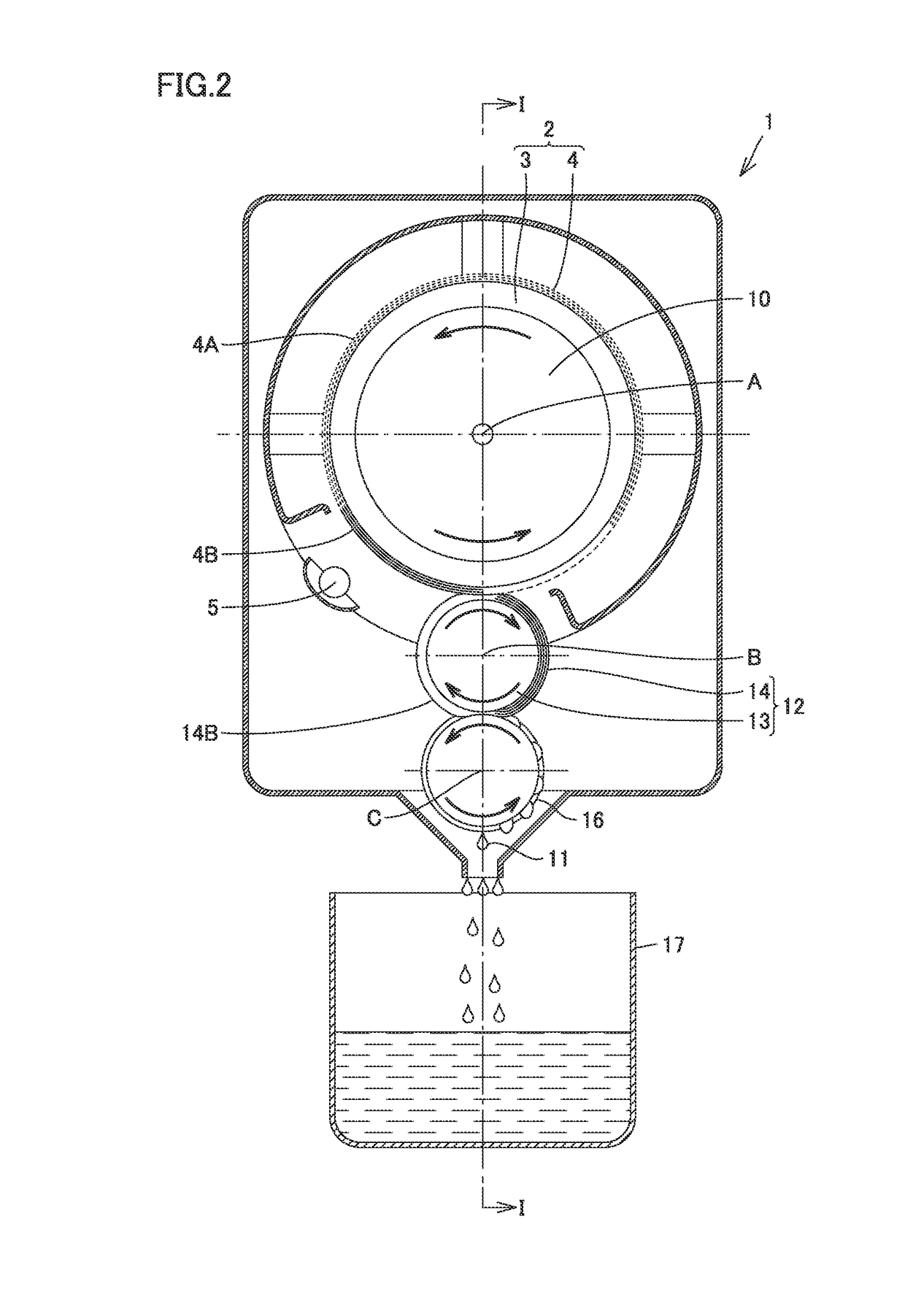
Image

Examples
first embodiment
[0019]In the present invention base material 3 is not limited to any particular shape as long as it is rotatable about a rotation shaft, and it may be in the form of a solid cylinder, a hollow cylinder, a solid triangular prism, a hollow triangular prism, a solid quadrangular prism, a hollow quadrangular prism, a solid polygonal prism, a hollow polygonal prism, a sphere having a round cross section, a sphere having an elliptical cross section, a disk, a flat plate, a polyhedron, a wire, or other indefinite shapes, although it is preferably a solid cylinder, a hollow cylinder, a disk, or a flat plate as it facilitates forming a layer of the macromolecular moisture absorbent, has consistency with a heated portion, allows an overall balance co-establishing moisture absorption and water releasing, and furthermore, allows efficient humidity control with the macromolecular moisture absorbent utilized.
[0020]Base material 3 is not limited to any particular material, either, and can be forme...
second embodiment
isture Absorbent
[0022]When the macromolecular moisture absorbent in the present invention as described above is implemented as zeolite, silica gel or the like, it does not require a heat source of high temperature such as required to desorb adsorbed moisture (e.g. 200 degrees centigrade) and thus requires small thermal energy. Furthermore, using zeolite, silica gel or the like is also advantageous in that it does not entail cooling to collect desorbed moisture as water and allows the moisture to be collected from the macromolecular moisture absorbent as it is.
[0023]The thickness of the layer of macromolecular moisture absorbent 4 is not limited to any particular thickness, however, it can be determined as appropriate considering its moisture absorption rate, thermal conductivity when it is heated, overall size, and the like. Excessively large thickness as a matter of course increases the amount of moisture that the layer of macromolecular moisture absorbent 4 singly contains therein...
third embodiment
etal Bonding)
[0025]Furthermore, FIG. 3 schematically shows an example of bonding macromolecular moisture absorbent 4 in the present invention when base material 3 is metal (the figure shows iron of a surface of SUS). A technique of bonding an organic matter such as resin and an inorganic matter such as metal is known for example for a heater from Japanese Patent Laying-Open No. 2013-007355 and WO2013 / 140845. For example, when base material 3 is metal (e.g., SUS), an oxide film on a surface of the metal is removed and thereafter an alkyl chain (a principal chain) of macromolecular moisture absorbent (e.g., N-isopropylacrylamide (NIPAM)) 4 is bonded via silane coupling 6 so that the inorganic matter, or the metal, and the inorganic matter, or macromolecular moisture absorbent 4, are strongly bonded together by strong bonding different from hydrogen bonding or van der Waals force. The metal's material, the silane coupling's type, macromolecular moisture absorbent 4's type are of course...
PUM
| Property | Measurement | Unit |
|---|---|---|
| temperature | aaaaa | aaaaa |
| temperature | aaaaa | aaaaa |
| hydrophilic | aaaaa | aaaaa |
Abstract
Description
Claims
Application Information