Hydraulic equipment

a technology of hydraulic equipment and hydraulic pump, which is applied in the direction of fluid couplings, positive displacement liquid engines, servomotors, etc., can solve the problems of reducing deteriorating the efficiency of hydraulic equipment, and excessive operating fluid

Inactive Publication Date: 2006-05-16
SAXA +1
View PDF10 Cites 23 Cited by
  • Summary
  • Abstract
  • Description
  • Claims
  • Application Information

AI Technical Summary

Problems solved by technology

Therefore, when the amount of operating fluid needed by the load fluctuates, an excess of operating fluid occurs.
However, each of the hydraulic pump and the driving source such as a heat engine or electric motor for driving the hydraulic pump is hard to keep a high efficiency in all the revolution ranges, whereby the efficiency in the hydraulic apparatus may deteriorate when the hydraulic pump changes its number of revolutions.
Also, the flow rate adjustment consumes the hydraulic energy as thermal energy, which may lower the efficiency in the hydraulic apparatus.
However, such a pump has a complicated structure and is expensive.

Method used


Image

  • Hydraulic equipment
  • Hydraulic equipment
  • Hydraulic equipment

Examples


Embodiment Construction

[0019]In the following, preferred embodiments of the present invention will be explained in detail with reference to the drawings.

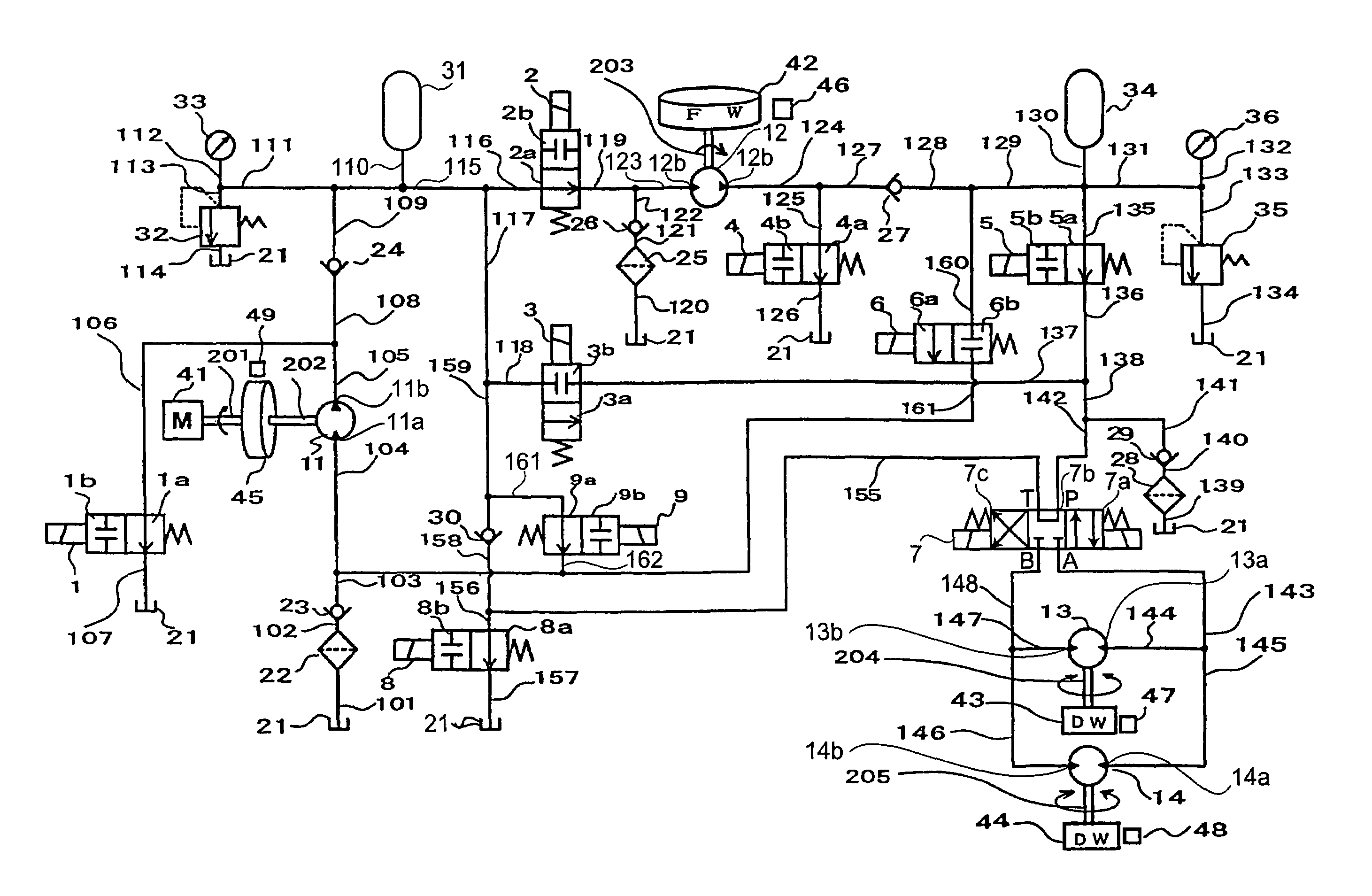
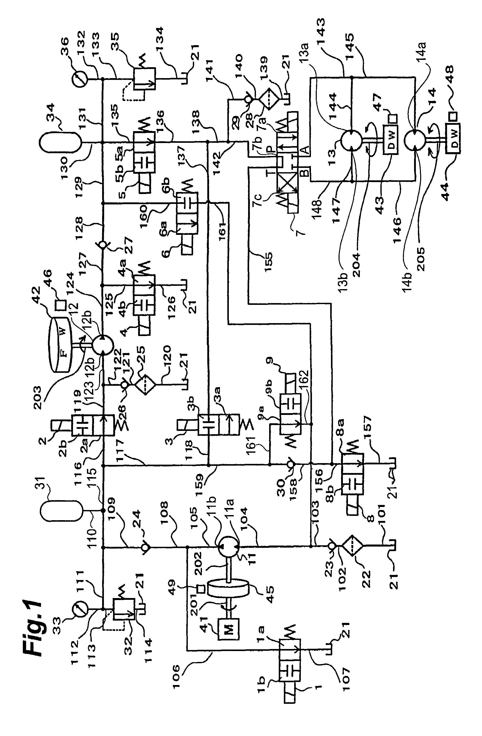
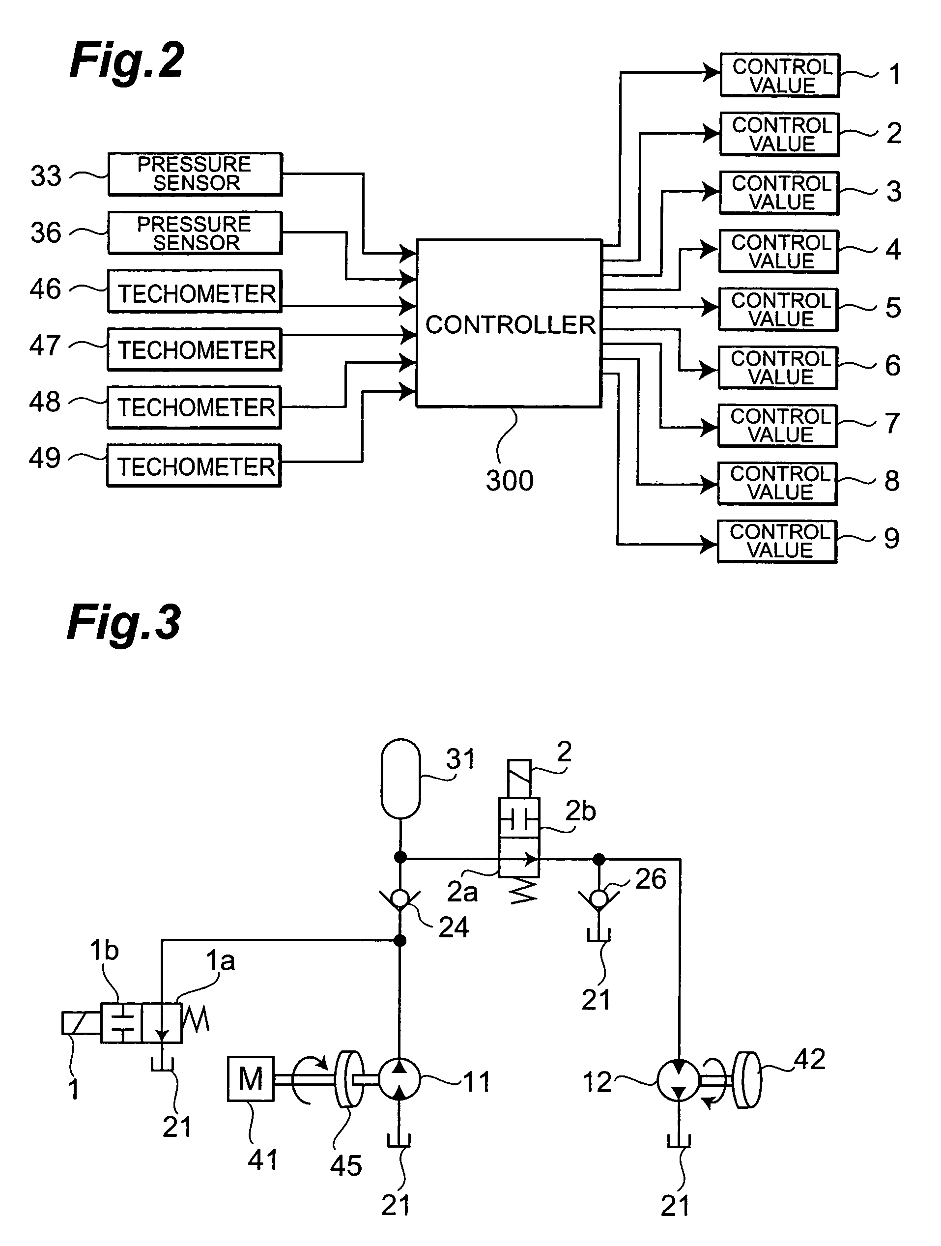
[0020]FIG. 1 is a hydraulic circuit diagram showing a hydraulic apparatus in accordance with the present invention employed in a driving system for a vehicle. In FIG. 1, number 41 refers to a driving source, which is preferably a heat engine in the vehicle, though other types of driving sources such as an electric motor may be used. An inertial element, which is specifically a flywheel 45, is attached to a shaft 201 of the driving source 41. The flywheel 45 is also known as a balance wheel, and accumulates a rotational energy when driven by the driving source 41 to rotate. A shaft 202 is connected to the center of the flywheel 45. By way of the shaft 201, the driving force from the driving source 41 is transmitted to a hydraulic pump (“third pump motor” in claims) 11 and drives the latter. When the driving source 41 has a large moment of inertia, i.e., wh...


PUM


Abstract

A hydraulic apparatus realizes the same function as that of a variable discharge pump by regulating a hydraulic device such as a control valve in a state always operated at a substantially constant number of revolutions with a high efficiency regardless of the type of a hydraulic pump driven by a driving source such as a heat engine or electric motor. This hydraulic apparatus drives a hydraulic pump with a driving source internally or additionally provided with a predetermined amount of inertia, so as to construct a fixed pressure hydraulic source, and further provides peripheral devices corresponding to a required load, so as to open / close a control valve according to a state of a load including an energy accumulating device, a hydraulic motor, or the like such that the load can be supplied with an operating fluid ranging from a low flow rate at a high pressure to a high flow rate at a low pressure.

Description

TECHNICAL FIELD[0001]The present invention relates to a hydraulic apparatus and, more particularly, relates to a hydraulic apparatus comprising a hydraulic pump driven by a driving source having a predetermined amount of inertia or a predetermined amount of moment of inertia, and a load driven by a hydraulic pressure generated by the hydraulic pump.BACKGROUND ART[0002]In a hydraulic apparatus in which a load such as a hydraulic motor is driven by a hydraulic pressure generated by a hydraulic pump of fixed discharge amount type, for example, the amount of operating fluid discharged from the hydraulic pump is fixed. Therefore, when the amount of operating fluid needed by the load fluctuates, an excess of operating fluid occurs. Therefore, means for changing the number of revolutions of the hydraulic pump and means for adjusting the flow rate by flow rate adjusting means such as a throttle valve or reducing valve have been employed in general in order to supply an amount of operating f...

Claims


Application Information

Patent Timeline
Patent Type & Authority Patents(United States)
IPC IPC(8): F15B11/02E02F9/22F15B11/00F15B11/16F15B21/14
CPCE02F9/2217F15B21/14F15B11/165F15B2211/7058F15B2211/205F15B2211/20569F15B2211/20576F15B2211/212F15B2211/265F15B2211/30505F15B2211/30525F15B2211/3056F15B2211/3116F15B2211/31594F15B2211/327F15B2211/50518F15B2211/615F15B2211/6309F15B2211/6336
Inventor SUZUKI, SHIGERUAOYAMA, KOUICHISHIMADA, SATORUSEKI, SUMIKOITOH, TAKAHIKO
Owner SAXA
Why Eureka
Try Eureka