Apparatus for extracting exhaust heat from waste heat sources while preventing backflow and corrosion

a technology of exhaust heat and exhaust fan, which is applied in the direction of corrosion-reducing boiler components, machines/engines, energy industry, etc., can solve the problems of backflow of exhaust into the cold, corrosion at the acid dewpoint, and non-operational engines

Inactive Publication Date: 2006-05-16
UNITED TECH CORP
View PDF13 Cites 21 Cited by
  • Summary
  • Abstract
  • Description
  • Claims
  • Application Information

AI Technical Summary

Benefits of technology

[0004]Briefly, in accordance with one aspect of the invention, a venturi is placed in each of a plurality of waste heat sources to produce a local pressure below the atmospheric ambient pressure, and a fan is provided to draw hot gases from a manifold passing through these venturis, through a heat exchanger, to the fan and out to ambient. In this way, when one of the waste heat sources is shut down, the hot gases from the other of the waste heat sources will not flow into that waste heat source and be condensed so as to cause corrosion.

Problems solved by technology

These elements are relatively benign at elevated temperatures where they remain in gaseous form, but on cooler surfaces the gas may condense and cause acid dewpoint corrosion (ADC).
This situation changes when one of the engines is disabled.
Now, higher pressure at the exhaust stack of the operating engine exhaust will cause backflow of exhaust into the cold, nonoperational engine.

Method used


Image

  • Apparatus for extracting exhaust heat from waste heat sources while preventing backflow and corrosion
  • Apparatus for extracting exhaust heat from waste heat sources while preventing backflow and corrosion

Examples


Embodiment Construction

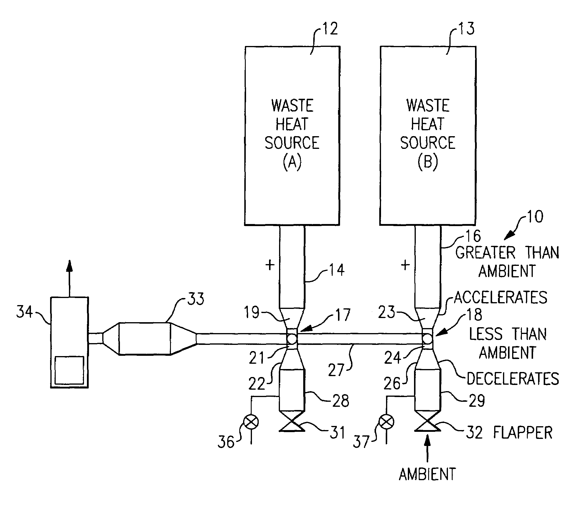
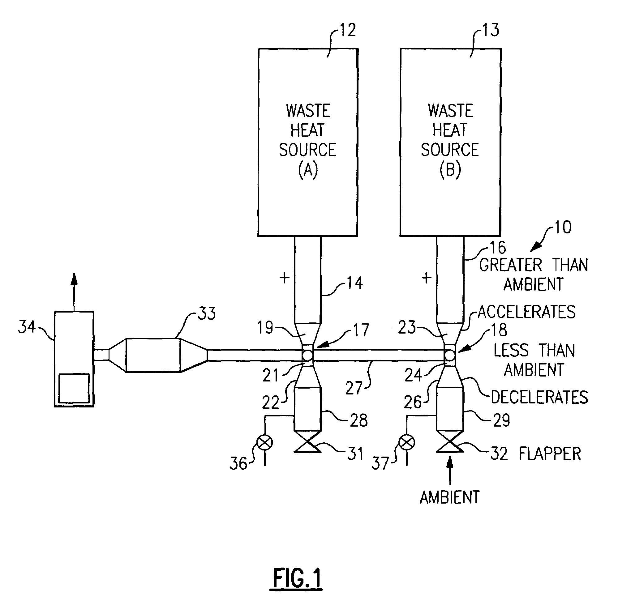
[0009]Referring now to FIG. 1, the invention is shown generally at 10 as applied to a heat recovery system for recovering waste heat from a plurality of waste heat sources as shown at 12 and 13. Although the invention will be described in terms of use with two waste heat sources, 12 and 13, it should be understood that the present invention is applicable to any number of such systems operating in parallel or to use with a single waste heat source.

[0010]One of the features of the present invention is to allow one or more of the waste heat sources to be in a nonoperating condition, or in a condition of operating at a lower speed, while one or more of the other waste heat sources in an operable condition at higher speeds. Normally, in these conditions, there is tendency for the hot gases from the operating waste heat source(s) to migrate to the nonoperating waste source(s), where it may condense and cause acid dewpoint corrosion (ADC). The present invention is intended to overcome this...


PUM

PropertyMeasurementUnit
temperaturesaaaaaaaaaa
pressureaaaaaaaaaa

Abstract

In a waste heat recovery system wherein a heat exchanger derives heat from an engine exhaust, a venturi is fluidly connected to an engine exhaust port so as to thereby increase the flow rate and reduce the pressure in a manifold which is fluidly connected between the venturis and the heat exchanger. A fan is provided downstream of the heat exchanger to draw hot gases from the manifold, through the heat exchanger and discharge it to ambient. But when the fan is not operating during periods in which the engine is operating, the lower pressure manifold will draw ambient air in through the fan and through the heat exchanger, with the ambient air then being entrained in the exhaust gases being discharged from an exhaust channel downstream of the venturi. In one embodiment, a plurality of heat sources are provided with each having its own venturi connected to the common low pressure manifold. One or more of the plurality of waste heat source may be nonoperative or operating at a lower speed, but because of the low pressure manifold, the hot gases from the operative/higher speed waste heat source will not flow to the nonoperative or slower running waste heat source. Check valves are provided to allow the discharge of hot gases to ambient from the exhaust channels but not allow the flow of ambient air into the exhaust channels. A bypass valve is provided to selectively allow for the flow of ambient air into the exhaust channel and into the manifold for purposes of dilution during periods in which the fan is in operation.

Description

BACKGROUND OF THE INVENTION[0001]This invention relates generally to waste heat recovery systems and, more particularly, to a system for recovering waste heat from engine exhausts having corrosive elements therein.[0002]Waste heat produced by a wide range of engines and industrial processes can be harnessed to provide benefits such as electricity, cooling, and water heating. Waste heat is often present in the form of a hot gas flow which is sometimes contaminated by corrosive elements such as sulfur and chlorine. These elements are relatively benign at elevated temperatures where they remain in gaseous form, but on cooler surfaces the gas may condense and cause acid dewpoint corrosion (ADC).[0003]Interconnection of hot gas waste heat streams is often constrained by the existence of ADC. For example, to operate some waste heat recovery device it may be desirable to combine the exhaust streams of two reciprocating engines burning moderate sulfur fuel. If both engines are operating, th...

Claims


Application Information

Patent Timeline
Patent Type & Authority Patents(United States)
IPC IPC(8): B60K6/04B01D19/00F01B31/00F01K13/02F01K19/00F01K21/06F02B35/00B60K6/20F01N13/10
CPCF01K23/065F02B35/00F22B1/1807F23G5/46F23G5/48F22B37/025F01N5/02F01N2470/30Y02T10/16F28D21/0003F28F19/00Y02T10/146Y02E20/30Y02T10/12Y02P80/15F01N13/00F01N13/10
Inventor RADCLIFF, THOMAS D.MCCORMICK, DUANEBILBOW, JR., WILLIAM
Owner UNITED TECH CORP
Why Eureka
Try Eureka