Fluid diode expansion device for heat pumps

a technology of expansion device and heat pump, which is applied in the direction of functional valve types, refrigeration components, light and heating apparatus, etc., can solve the problems of expansion device wear, adversely affecting the operation and reliability of the system, and the prone to wear of the pipe, etc., and achieves the effect of low drag coefficient and high drag coefficien

Inactive Publication Date: 2006-05-16
CARRIER CORP
View PDF25 Cites 19 Cited by
  • Summary
  • Abstract
  • Description
  • Claims
  • Application Information

AI Technical Summary

Benefits of technology

[0005]The inventive heat pump expansion device consists of a flow resistance device that has a different resistance to flow depending on the flow direction through this device. The flow resistance device is fixed or rigidly mounted relative to first and second fluid passages so that it avoids the wear problems of the moveable piston in the prior art. The fluid flow resistance device in several examples of the invention is a fixed obstruction about which the refrigerant must flow when traveling through the expansion device. The flow resistance device has features on one side that create a low drag coefficient when the refrigerant flows in one direction but a high drag coefficient when the refrigerant flows in the opposing direction.
[0006]Accordingly, the present invention provides a reliable, inexpensive expansion device that is not as prone to wear and reduces reliability problems.

Problems solved by technology

The piston is prone to wear, which adversely effects the operation and reliability of the system due to undesirably large tolerances and contamination.
This adversely impacts the expansion device wear, lubrication and results in higher loads during transient conditions of operation.

Method used


Image

  • Fluid diode expansion device for heat pumps
  • Fluid diode expansion device for heat pumps

Examples


Embodiment Construction

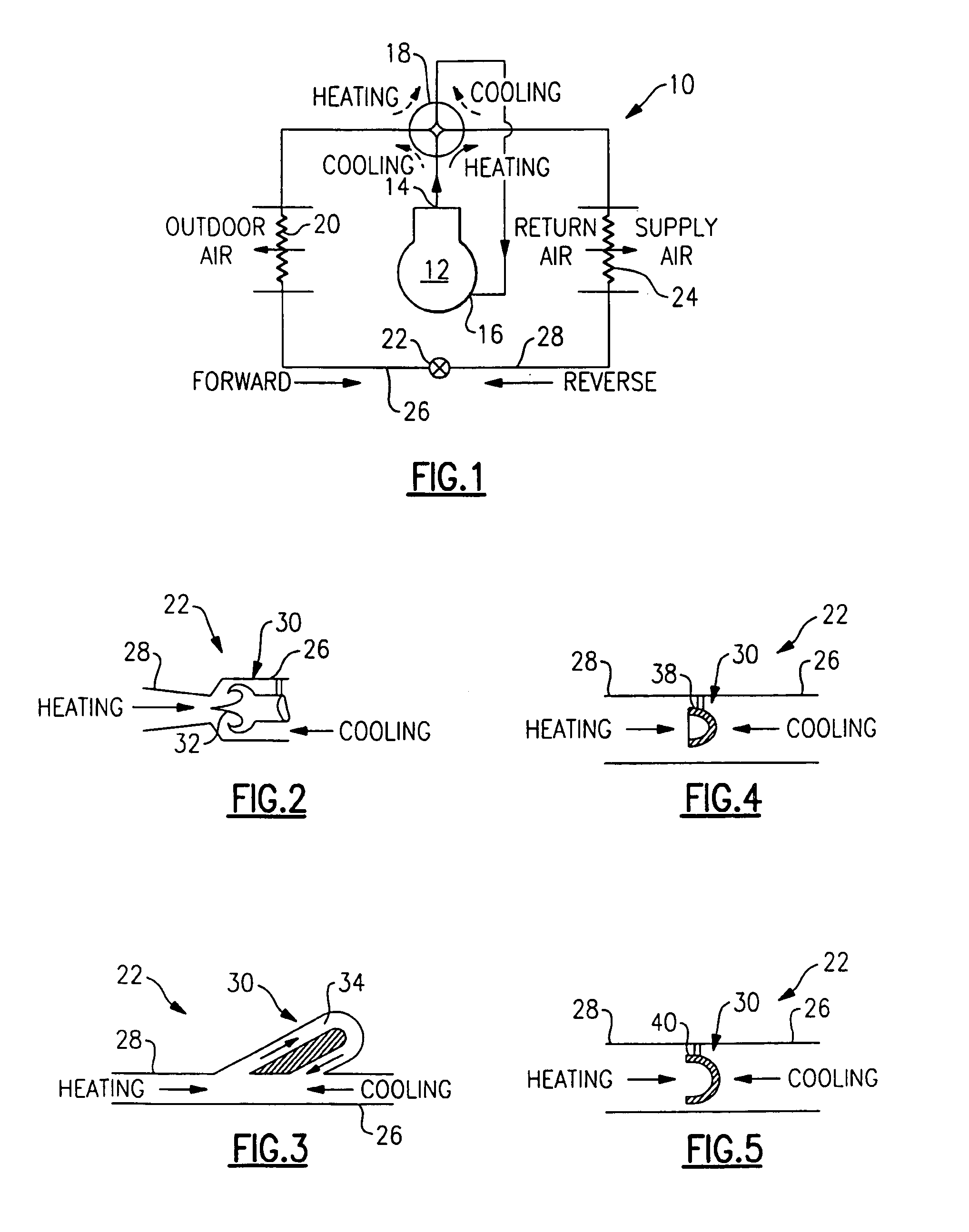
[0013]A heat pump 10 utilizing the present invention and capable of operating in both cooling and heating modes is shown schematically in FIG. 1. The heat pump 10 includes a compressor 12. The compressor 12 delivers refrigerant through a discharge port 14 that is returned back to the compressor through a suction port 16.

[0014]Refrigerant moves through a four-way valve 18 that can be switched between heating and cooling positions to direct the refrigerant flow in a desired manner (indicated by the arrows associated with valve 18 in FIG. 1) depending upon the requested mode of operation, as is well known in the art. When the valve 18 is positioned in the cooling position, refrigerant flows from the discharge port 14 through the valve 18 to an outdoor heat exchanger 20 where heat from the compressed refrigerant is rejected to a secondary fluid, such as air. The refrigerant flows from the outdoor heat exchanger 20 through a first fluid passage 26 of the inventive expansion device 22. Th...


PUM


Abstract

An expansion device for the heat pump applications consists of a flow resistance device that has a different resistance to refrigerant flow depending on the flow direction through this device. The flow resistance device has no moving parts so that it avoids the damage, wear and contamination problems of the moveable piston in the prior art. The flow resistance device is a fixed obstruction about which the fluid must flow when traveling through the expansion device.

Description

BACKGROUND OF THE INVENTION[0001]This invention relates to an expansion device for a heat pump.[0002]Heat pumps employ a compressor, an indoor heat exchanger, an outdoor heat exchanger, an expansion device and 4-way reversing valve, to switch operation between cooling and heating modes. Heat pumps utilize an expansion device through which the refrigerant flow expands from high pressure and temperature to low pressure and temperature. Different size restriction of the expansion device is required for proper system operation depending upon whether the heat pump is in a cooling or heating mode of operation. Obviously, when the system is operating in cooling or in heating mode, the direction of the refrigerant flow through the expansion device is reversed.[0003]Prior art heat pump systems with single expansion devices use a moveable piston that moves in a first direction in which its flow resistance is substantially higher than when it is moved in an opposite second direction. The first...

Claims


Application Information

Patent Timeline
Patent Type & Authority Patents(United States)
IPC IPC(8): F25B41/06F16K15/00F25B13/00F25B27/00F25B39/02
CPCF25B13/00F25B41/062F25B2500/21F25B2500/01F25B2500/05F25B2341/061F25B41/38
Inventor LIFSON, ALEXANDERDOBMCIER, THOMAS J.TARAS, MICHAEL F.
Owner CARRIER CORP
Why Eureka
Try Eureka