Dual clutch automatic transaxle

a dual clutch, automatic technology, applied in mechanical equipment, transportation and packaging, gearing, etc., can solve the problems of affecting fuel economy, narrow and short engine compartments of such vehicles, and the loss of parasitic parasitic losses is only slightly higher, so as to reduce the length of the transaxle

Inactive Publication Date: 2006-05-16
FORD GLOBAL TECH LLC
View PDF24 Cites 33 Cited by
  • Summary
  • Abstract
  • Description
  • Claims
  • Application Information

AI Technical Summary

Benefits of technology

[0006]A transaxle according to this invention is a layshaft transaxle having dual friction clutches and two final drive pinions. The sixth forward drive gear is located on an idler shaft, which transmits torque to an output shaft associated with particular gear ratios, e.g., odd-numbered gear ratios. A driving gear for the fifth gear ratio is also an idler gear for the sixth gear ratio. Producing the sixth gear in this way allows a substantial reduction in length of the transaxle.
[0007]It is an advantage of this invention that the axial dimension of the transaxle, its lateral dimensions when installed in the vehicle, is reduced sufficiently to accommodate an I6 engine in the engine compartment. It is another advantage that its longitudinal dimension, as installed, provides sufficient space for V6 engines in the engine compartment.

Problems solved by technology

Automatic transmissions for transmitting power between an input and an output, either over a continuously variable range of speed ratios or in discrete step changes among speed ratios, have associated with them several sources of parasitic losses, which adversely affect fuel economy.
These losses are associated with a torque converter, open hydraulic friction clutches and brakes, hydraulic pump, and gear meshes.
Dual clutch transmissions have parasitic losses only slightly higher than ASM transmissions.
The engine compartments of such vehicles are both narrow and short.

Method used


Image

  • Dual clutch automatic transaxle
  • Dual clutch automatic transaxle
  • Dual clutch automatic transaxle

Examples


Embodiment Construction

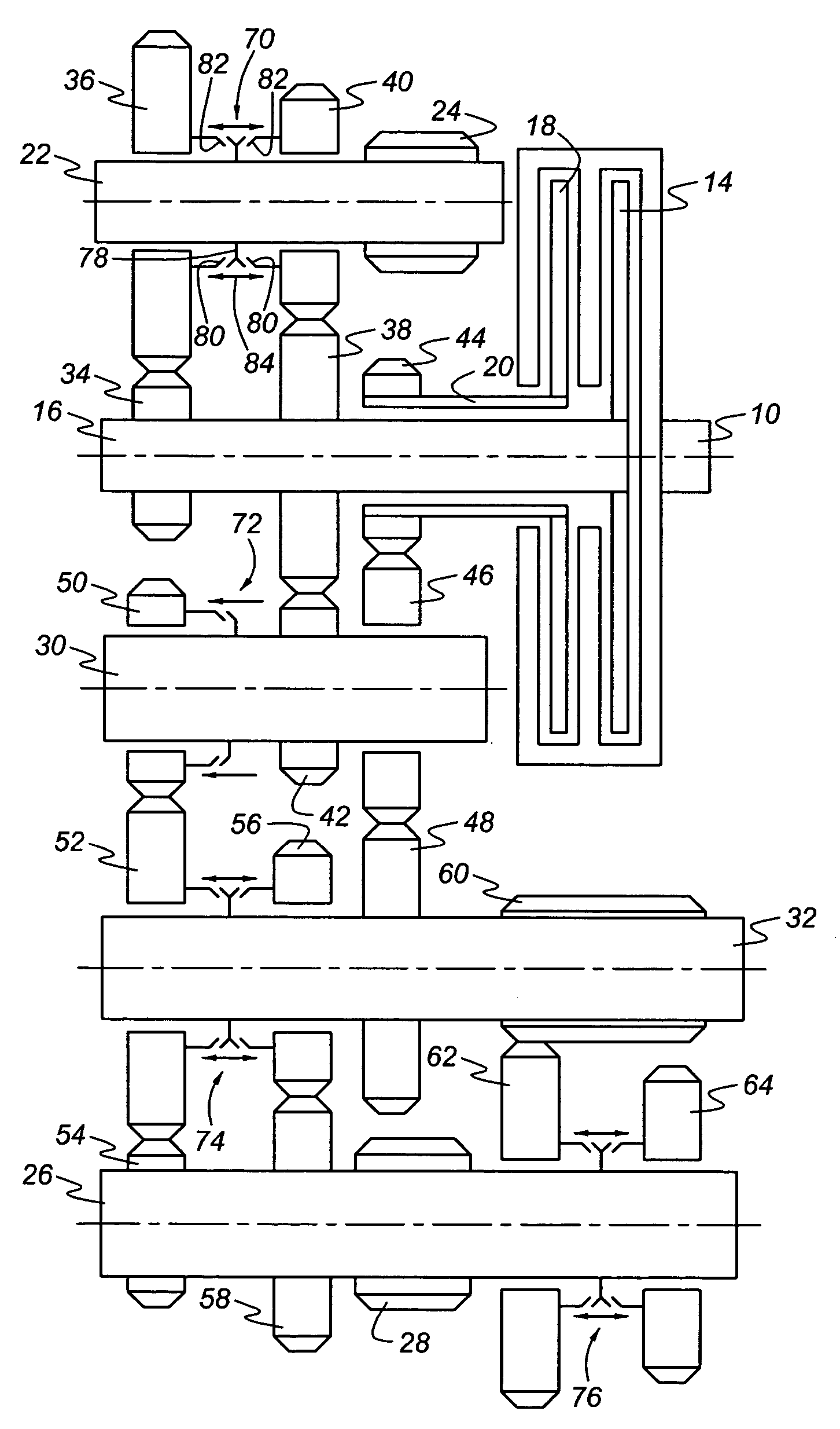
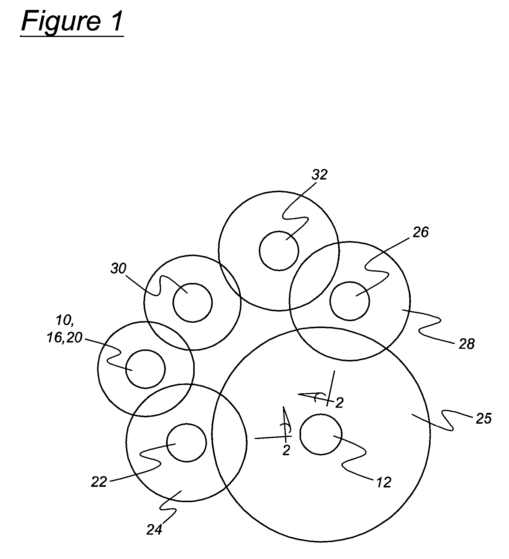
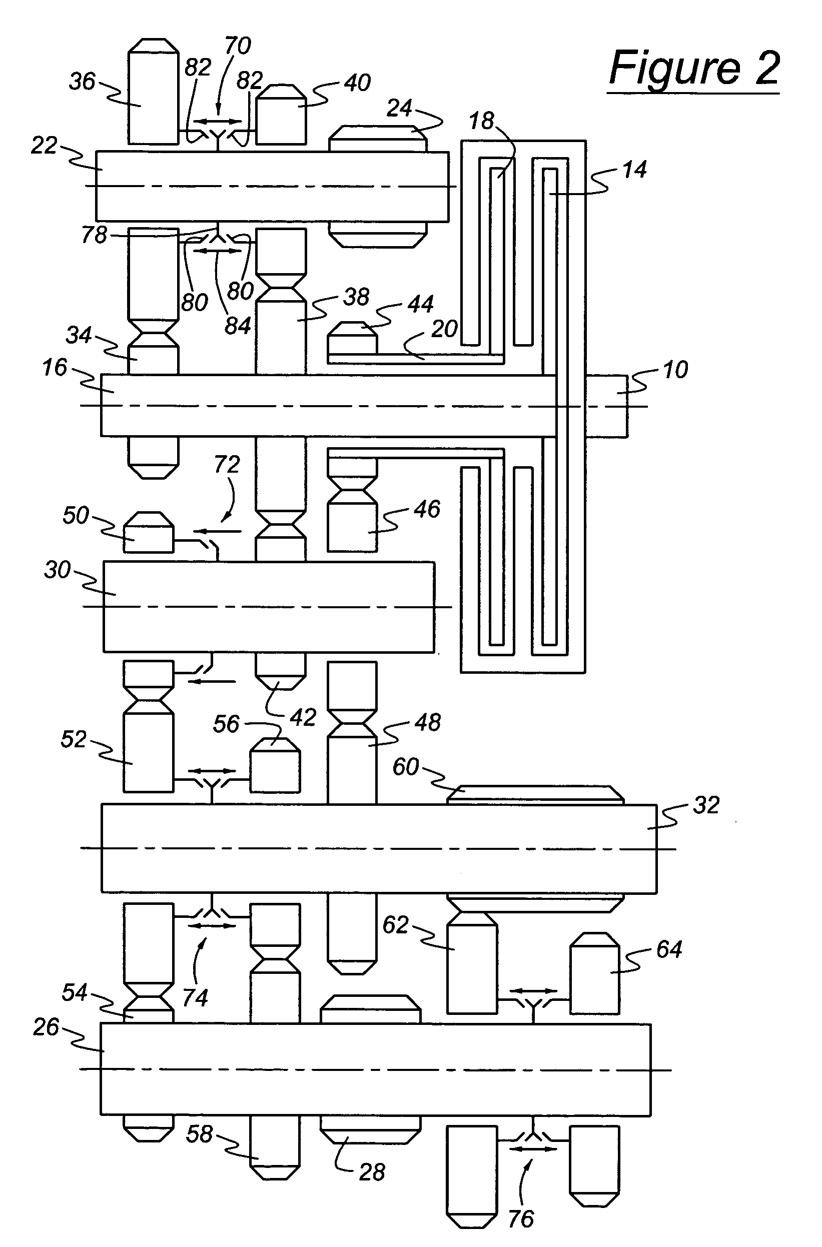
[0017]Referring to FIGS. 1 and 2, a transmission according to the present invention includes an input 10 for driveably connecting a power source, such as an internal combustion engine or electric motor, to the transmission, and an output 12 for driving a load, such as the driven wheels of a motor vehicle, through a powertrain that may include a drive shaft, differential mechanism, and axle shafts. A first friction clutch 14, consisting of a clutch housing and a clutch disc, alternately connects and disconnects a first input shaft 16 as clutch 14 is engaged and disengaged, respectively. A second friction clutch 18, consisting of a clutch housing and a clutch disc, connects and disconnects a second input shaft 20 as clutch 18 is engaged and disengaged, respectively.

[0018]A first output shaft 22 supports a first output pinion 24, which is secured to shaft 22 in continuous meshing engagement with an output gear 25, secured to output 12. A second output shaft 26 supports a second output ...


PUM


Abstract

A multiple speed transaxle includes first and second input shafts, first and second output shafts, a layshaft, an idler shaft, a first set of selectable torque paths between the first input shaft and first output shaft, a second set of selectable torque paths between the second input shaft and the second output shaft, the second set including the layshaft and idler shaft, and a selectable torque path between the first input shaft and second output shaft including the layshaft and idler shaft.

Description

BACKGROUND OF THE INVENTION[0001]This invention relates to automatic transmissions having a layshaft kinematic arrangement, particularly to automatic transaxles having dual input clutches, but no torque converter.[0002]Automatic transmissions for transmitting power between an input and an output, either over a continuously variable range of speed ratios or in discrete step changes among speed ratios, have associated with them several sources of parasitic losses, which adversely affect fuel economy. These losses are associated with a torque converter, open hydraulic friction clutches and brakes, hydraulic pump, and gear meshes.[0003]To improve fuel economy in a motor vehicle having an automatic transmission, an automated shift manual (ASM) transmission can be used to eliminate or substantially reduce all of these parasitic losses except gear mesh losses. An ASM transmission generally performs gear ratio changes by first interrupting torque transmitted from the engine to the transmiss...

Claims


Application Information

Patent Timeline
Patent Type & Authority Patents(United States)
IPC IPC(8): F16H3/08F16H3/00F16H3/085F16H3/093F16H3/095
CPCF16H3/006F16H3/093F16H2003/0931F16H2200/0052Y10T74/19228Y10T74/19233Y10T74/19288Y10T74/19284F16H2200/0056
Inventor JANSON, DAVIDBALDWIN, REID
Owner FORD GLOBAL TECH LLC
Why Eureka
Try Eureka