
System and method for automatic drilling to maintain equivalent circulating density at a preferred value

Active Publication Date: 2006-05-16
NOBLE SERVICES CO LLC
View PDF27 Cites 85 Cited by
  • Summary
  • Abstract
  • Description
  • Claims
  • Application Information

AI Technical Summary

Problems solved by technology

Drilling wells in subsurface formations for oil and gas wells is expensive and time consuming.
The cost associated with drilling a well is primarily time dependent.
However, cost and time associated with well construction can increase substantially if wellbore instability problems or obstacles are encountered during drilling.
Because of the complex nature of drilling, a weight on bit that is optimum for one set of conditions may not be optimum for another set of conditions.
A limitation of using an optimum weight on bit determined from a drill off test is that the weight on bit value thus determined is optimum only for the particular set of conditions experienced during the test, such as drilling fluid (“mud”) flow rate, the type of formation being drilled, temperature and pressure conditions, etc.
As a result, the weight on bit determined in the drill off test may no longer be optimum.
Problems that may be encountered during drilling operations include events such as sticking (or stuck pipe), kick, loss of circulation (or formation fracture), and washout.
Sticking occurs when the drill string gets stuck in the wellbore, such as due to the build-up of cuttings in the wellbore due to inefficient clean out or collapse of the wellbore.
Washout is excessive enlargement of the wellbore caused by solvent and erosion action by drilling fluid.
Washout can cause severe damage to the formation, contamination of the connate formation fluids, and can waste costly drilling mud.
Typically, the lower pressure limit for wellbore stability is the greater of the fluid pressure in the drilled formations, or the amount of pressure needed to avoid wellbore collapse.
The upper pressure limit for wellbore stability is typically the lowest fracture pressure of the drilled formations exposed to the wellbore.
When drilling fluid pressure exceeds the formation fracture pressure, there is a risk of creating or opening fractures, resulting in loss of drilling fluid circulation and damage to the affected formation.
However, there are often large discrepancies between the measured and calculated pressures due to uncertainties in the calculations, poor knowledge of pressure losses through certain components of the circulation system, changes in the mud density and rheology with temperature and pressure, and / or poor application of hydraulics models for different mud systems.
Operating outside these limits can lead to expensive lost circulation, differential sticking, and packing-off incidents.
How the driller controls the release of the drill string is somewhat unpredictable, and is related to the level of attention the driller has to give to a number of different tasks.

Method used


Image

  • System and method for automatic drilling to maintain equivalent circulating density at a preferred value
  • System and method for automatic drilling to maintain equivalent circulating density at a preferred value
  • System and method for automatic drilling to maintain equivalent circulating density at a preferred value

Examples


Embodiment Construction

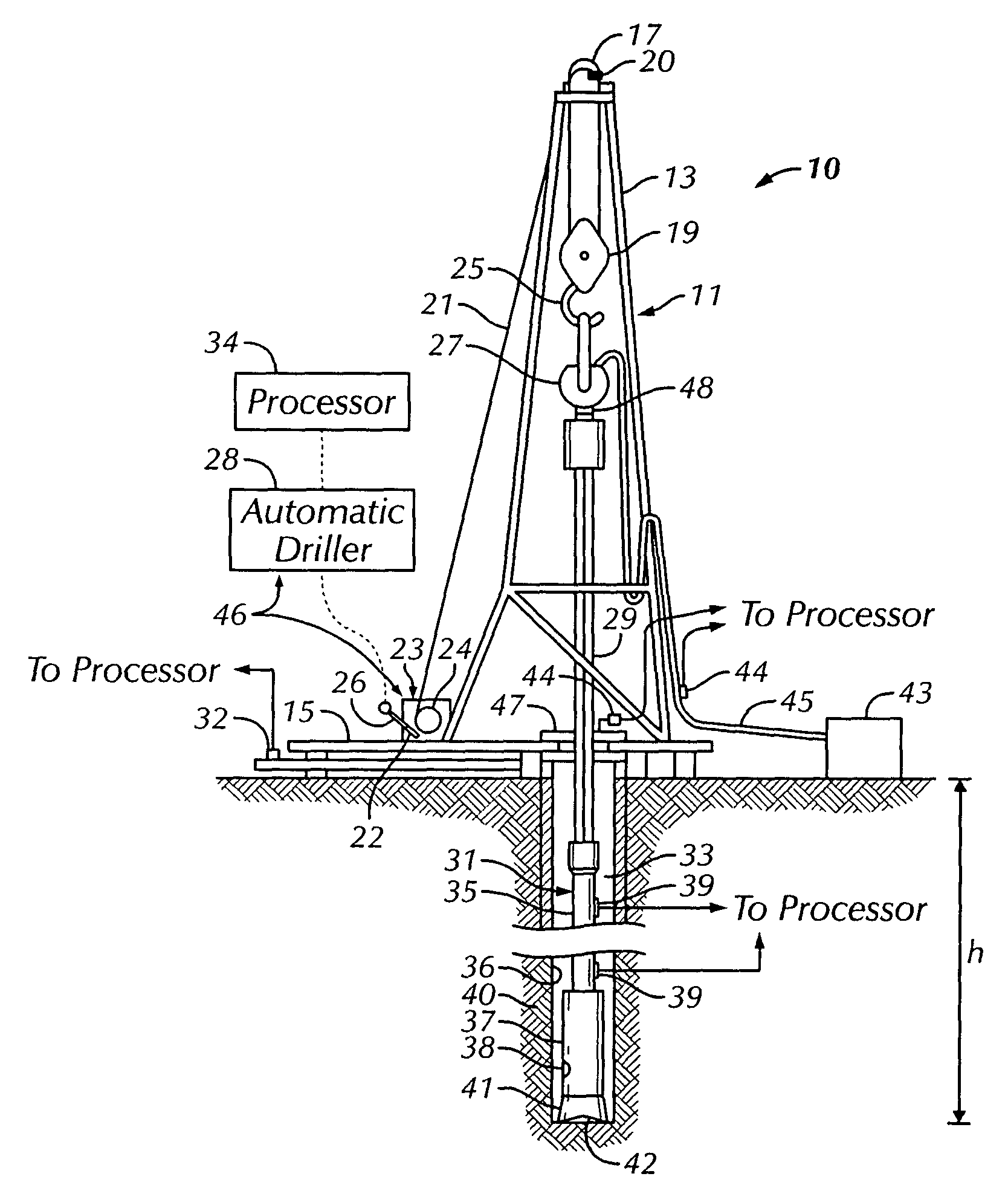
[0026]FIG. 1 shows one example of a rotary drilling system 10 in accordance with one embodiment of the present invention. The drilling system 10 includes a drilling rig 11. In the particular embodiment shown, the drilling rig 11 is a land rig. However, it will be apparent to those skilled in the art that the method and system of the present invention equally apply to any drilling system, including marine drilling rigs such as jack-up rigs, semi-submersibles, drill ships, and the like. Additionally, although the drilling rig 11 is a conventional rotary rig, wherein drill string rotation is performed by a rotary table turning a Kelly bushing, those skilled in the art will appreciate that the invention is applicable to other drilling technologies, such as top drive, power swivel, downhole hydraulic motors, coiled tubing units, and the like.

[0027]The drilling rig 11 includes a mast 13 supported on a rig floor 15. The drilling rig 11 also includes lifting gear comprising a crown block 17...


PUM


Abstract

A drilling system includes a pressure sensor disposed on a drill string in the wellbore, the sensor responsive to pressure of a drilling fluid disposed in an annular space between a wall of the wellbore and the drill string, and a processor operatively coupled to the pressure sensor. The processor is adapted to operate a drill string release controller to release the drill string into the wellbore so as to maintain an equivalent density of the drilling fluid substantially at a selected value. A method for automatically drilling a wellbore includes measuring pressure of a drilling fluid in an annular space between a wall of the wellbore and a drill string in the wellbore, and automatically controlling a rate of release of the drill string in response to the measured pressure so as to maintain an equivalent density of the drilling fluid substantially at a selected value.

Description

BACKGROUND OF INVENTION[0001]1. Field of the Invention[0002]The invention relates generally to drilling boreholes through subsurface formations. More particularly, the invention relates to a method and a system for controlling the rate of release of a drill string to maintain equivalent density at a selected value during drilling.[0003]2. Background Art[0004]Drilling wells in subsurface formations for oil and gas wells is expensive and time consuming. Formations containing oil and gas are typically located thousands of feet below the earth surface. Therefore, thousands of feet of rock and other geological formations must be drilled through in order to establish production. While many operations are required to drill and complete a well, perhaps the most important is the actual drilling of the borehole. The cost associated with drilling a well is primarily time dependent. Accordingly, the faster the desired penetration depth is achieved, the lower the cost for drilling the well. Howe...

Claims


Application Information

Patent Timeline
IPC IPC(8): E21B19/08E21B44/06E21B44/00E21B44/02
CPCE21B44/02E21B44/005
Inventor PINCKARD, MITCHELL D.NIEDERMAYR, MICHAELKING, CHARLES H.
Owner NOBLE SERVICES CO LLC
Features
  • Generate Ideas
  • Intellectual Property
  • Life Sciences
  • Materials
  • Tech Scout
  • Unparalleled Data Quality
  • Higher Quality Content
  • 60% Fewer Hallucinations
Learn More