Exhaust pipe structure of vehicle with low floor

a technology of exhaust pipe and low floor, which is applied in the direction of machines/engines, cycles, cycle equipment, etc., can solve the problems of low degree of freedom in design, and achieve the effect of efficient configuration, reduced size of low floor type vehicles, and efficient arrangemen

Inactive Publication Date: 2006-05-16
HONDA MOTOR CO LTD
View PDF14 Cites 14 Cited by
  • Summary
  • Abstract
  • Description
  • Claims
  • Application Information

AI Technical Summary

Benefits of technology

[0021]The space is effectively utilized by making the first exhaust pipe connected to the rear cylinder in the bank pass over the power unit and further extending it downward via the space which is the opening substantially U-shaped when the opening is viewed from the top as described above, and the first exhaust pipe can be connected to the second exhaust pipe connected to the front cylinder in the bank. Therefore, the plural exhaust pipes for the longitudinal V-type engine can be efficiently arranged.
[0022]As the exhaust member is configured so that exhaust air from the exhaust member provided to the rear of the transmission unit hits the first and second exhaust pipes, exhaust in the first and second exhaust pipes can be controlled so that the exhaust is at desired temperature by the exhaust air. Particularly, both can be simultaneously cooled by cooling the first and second exhaust pipes and exhaust by exhaust air after the exhaust air cools the transmission unit, so that another cooling means is not required to be provided and the size of the low floor type vehicle can be reduced.
[0023]Also, although the second exhaust pipe is extended on one side of the front of the V-type engine, the first and second exhaust pipes are not extended in the crankcase on the other side of the front of the V-type engine. As the oil filter and the oil cooler which are respectively functional components for lubricating and cooling oil for the engine can be provided to the crankcase on the other side of the front of the V-type engine, space may be effectively utilized in which no exhaust pipe is extended, so that the size of the low floor type vehicle can be effectively arranged.
[0024]As exhaust air from the exhaust member hits the vicinity of the part in which the first exhaust pipe and the second exhaust pipe are collected, exhaust in the first and second exhaust pipes is cooled together and the temperature can be controlled, the configuration is efficient.
[0025]Also, an exhaust sensor is provided to the part of the first and second exhaust pipes which exhaust air hits, the exhaust sensor can be cooled by the exhaust air. As the thermal effect by exhaust of the exhaust sensor can be reduced, the configuration is advantageous to hold the function and the performance of the exhaust sensor. For example, injection via a fuel injection valve of an intake system can always be satisfactorily controlled by the exhaust sensor.

Problems solved by technology

Therefore, space for the two exhaust pipes is required to be secured in the same position and the degree of freedom in design is low.

Method used


Image

  • Exhaust pipe structure of vehicle with low floor
  • Exhaust pipe structure of vehicle with low floor
  • Exhaust pipe structure of vehicle with low floor

Examples


Embodiment Construction

[0054]Referring to the attached drawings, embodiments of the invention will be described below. “Front”, “rear”, “right”, “left”, “upper” and “lower” denote each position of a vehicle viewed from a rider, “Fr” means the front, “Rr” means the rear, “R” means the right, “L” means the left and “CL” means the center in the width of the body (the center of the body). The drawings shall be viewed using these direction indicators.

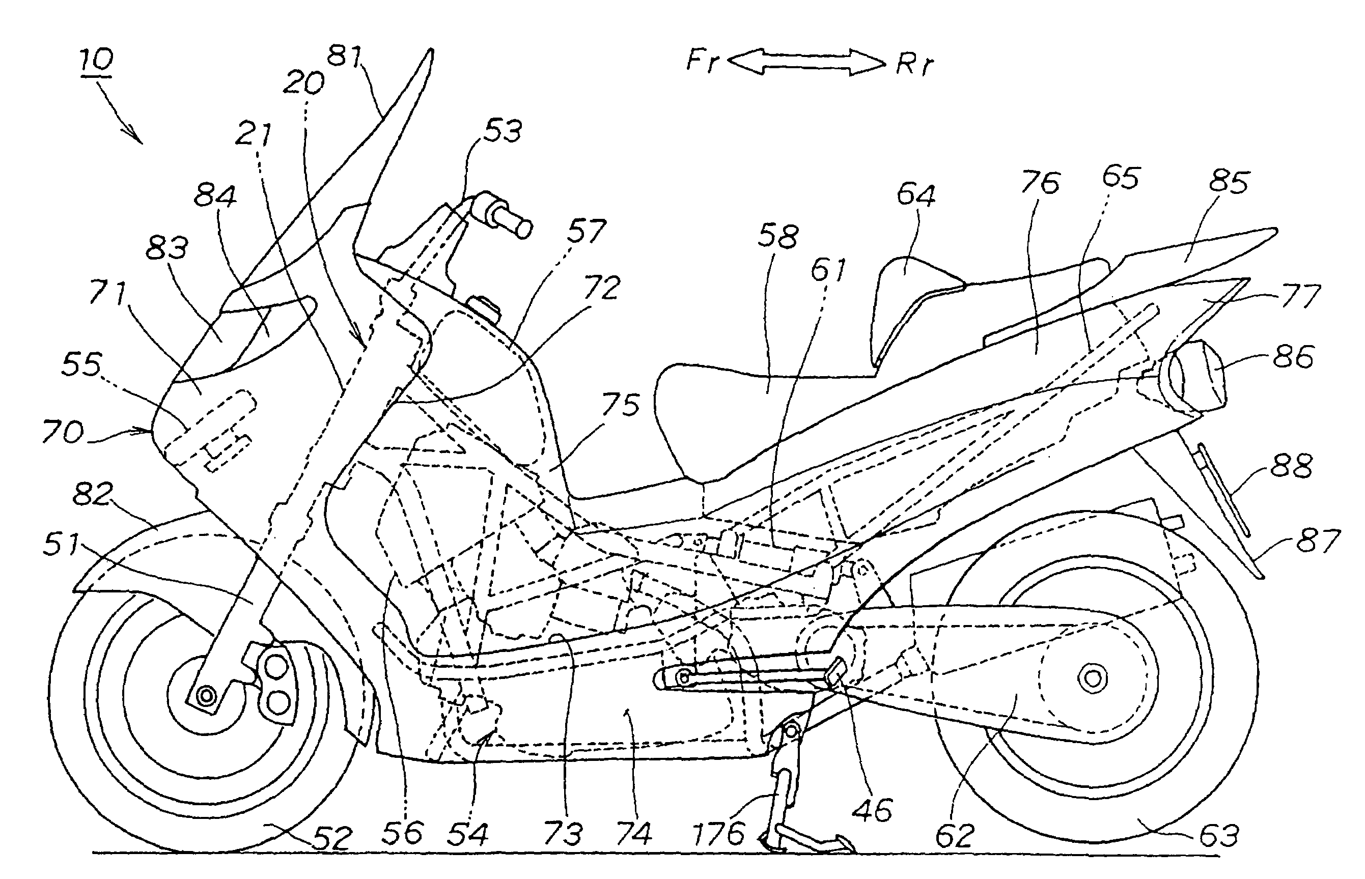
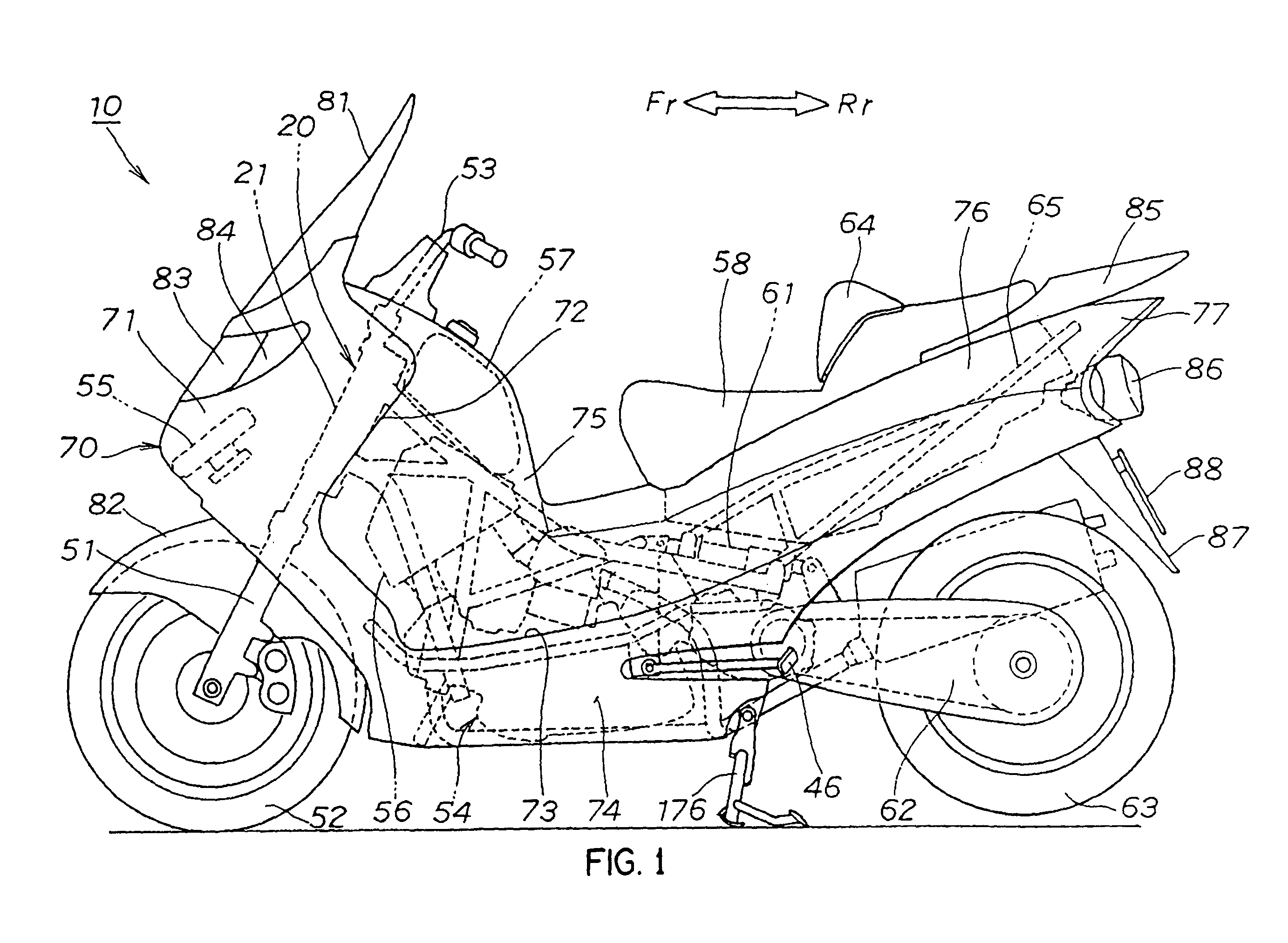
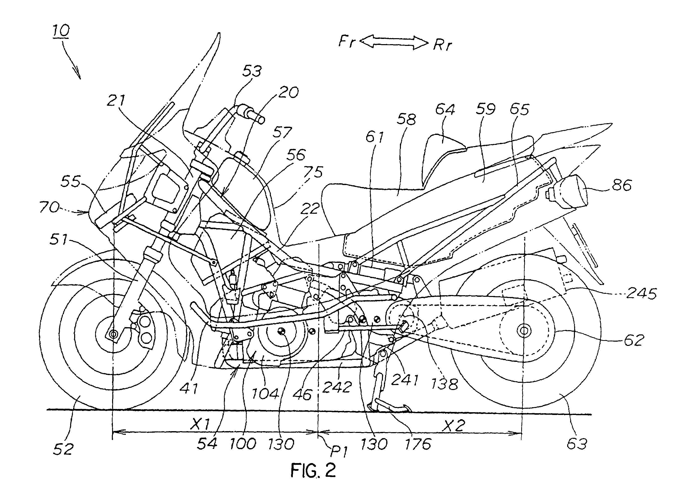
[0055]First, the whole configuration of a low floor type vehicle 10 will be described. FIG. 1 is a left side view 1 showing the low floor type vehicle 10 and showing a configuration in which a body cover 70 is attached. FIG. 2 is a left side view 2 showing the low floor type vehicle 10 and showing a configuration in which the body cover is detached. FIG. 3 is a plan showing the low floor type vehicle 10 and showing the configuration in which the body cover is detached.

[0056]The low floor type vehicle 10 is mainly composed of a body frame 20, a front fork 51 attach...


PUM


Abstract

A low floor vehicle is a scooter-type motorcycle in which a power unit with a longitudinal V-type engine is mounted below a low floor. The power unit is substantially U-shaped when the power unit is viewed from the top by configuring the transmission unit of the power unit so that the transmission unit is connected to the engine on one side of the V-type engine, is extended backward on one side of the vehicle and drives a chain drive mechanism so as to drive a rear wheel from the other side of the vehicle in the vicinity of a pivot of a swing arm for the rear wheel. A first exhaust pipe connected to a rear cylinder in a bank of the V-type engine is extended backward from the cylinder, the rear end is extended downward via space which is an opening substantially U-shaped when the opening is viewed from the top, the lower end is extended backward and the rear end is connected to a second exhaust pipe connected to a front cylinder in the bank of the V-type engine.

Description

BACKGROUND OF THE INVENTION[0001]1. Field of the Invention[0002]The present invention relates to a technique for improving an exhaust pipe structure of a vehicle with a low floor.[0003]2. Description of the Related Art[0004]Various techniques are used for mounting a power unit below a body frame in a vehicle with a low floor, such as a scooter-type motorcycle or a scooter-type three-wheeled vehicle. For example, Japanese published unexamined patent application No. 2001-88763 (see FIG. 2 on pp. 3 and 4) discloses such a technique.[0005]Referring to FIG. 28, the outline of a conventional type low floor type vehicle as disclosed in patent application No. 2001-88763 is described below. FIG. 28 is a schematic diagram showing the conventional low floor type vehicle of Japanese published unexamined patent application No. 2001-88763. A conventional low floor type vehicle 300 is a scooter type motorcycle in which a power unit 320 is mounted in a double cradle type body frame under 310 and un...

Claims


Application Information

Patent Timeline
Patent Type & Authority Patents(United States)
IPC IPC(8): B62D63/04B62K11/00B62J31/00B62K19/30B62M7/02F01N13/00F01N13/08F01N99/00
CPCB62K19/30B60Y2200/12B62K2202/00B60Y2200/126B60K13/04B62K11/00
Inventor TAKENAKA, MASAHIKOINAYAMA, YOICHI
Owner HONDA MOTOR CO LTD
Why Eureka
Try Eureka