Al technical title is built by PatSnap Al team. It summarizes the technical point description of the patent document.
a technology of electrical connectors and assembly parts, applied in the direction of connection contact material, coupling device connection, instruments, etc., can solve the problems of reducing dielectric strength, flashing or arcing to ground, and reducing pressure within the cavity
Inactive Publication Date: 2006-05-16
THOMAS & BETTS INT INC
View PDF71 Cites 61 Cited by
Summary
Abstract
Description
Claims
Application Information
AI Technical Summary
This helps you quickly interpret patents by identifying the three key elements:
Problems solved by technology
Method used
Benefits of technology
[0011]It is an object of the invention to provide separable electrical connectors, which upon disassembly under load, prevent flashover from occurring at the interface of the connectors.
[0012]It is a further object of the invention to provide a separable electrical connector, such as a power cable elbow connector and loadbreak bushing insert, having a modified interface which is vented to prevent a decrease in air pressure therebetween and a resulting decrease in dielectric strength of the air causing a flashover.
[0013]It is still a further object of the invention to provide a power cable elbow connector and loadbreak bushing insert having an indicator band formed on the bushing insert and which is vented to prevent a decrease in air pressure therebetween and a resulting decrease in dielectric strength of the air causing a flashover.
Problems solved by technology
During initial movement of the loadbreak connectors in the disassembly operation, the volume of air in the elbow cavity increases but is sealed off at the elbow cuff resulting in a decrease in pressure within the cavity.
Although this is a transient condition, it occurs at a critical point in the disassembly operation and can result in dielectric breakdown of the opening interface causing a flashover or arc to ground.
The lower pressure in the cavity reduces the dielectric strength of the air along the connection interface possibly resulting in flashover.
One drawback with loadbreak connectors of the prior art is the difficulty involved in inserting one end of the loadbreak bushing insert into the power elbow connector and inserting the opposite end of the loadbreak bushing insert into a bushing well.
Other drawbacks with these type of connectors relate to the problems encountered during manufacturing.
Even when trimmed properly, mold parting lines on the connector interface surfaces may disrupt the required connector seal and result in an electrical short.
Also, the mold cavities are typically prone to contaminants, which may in turn be imparted onto the electrical interface of the connector resulting in a scrapped part.
Method used
Image
Click on the blue label to locate the original text in one second.
Reading with bidirectional positioning of images and text.
Examples
Embodiment Construction
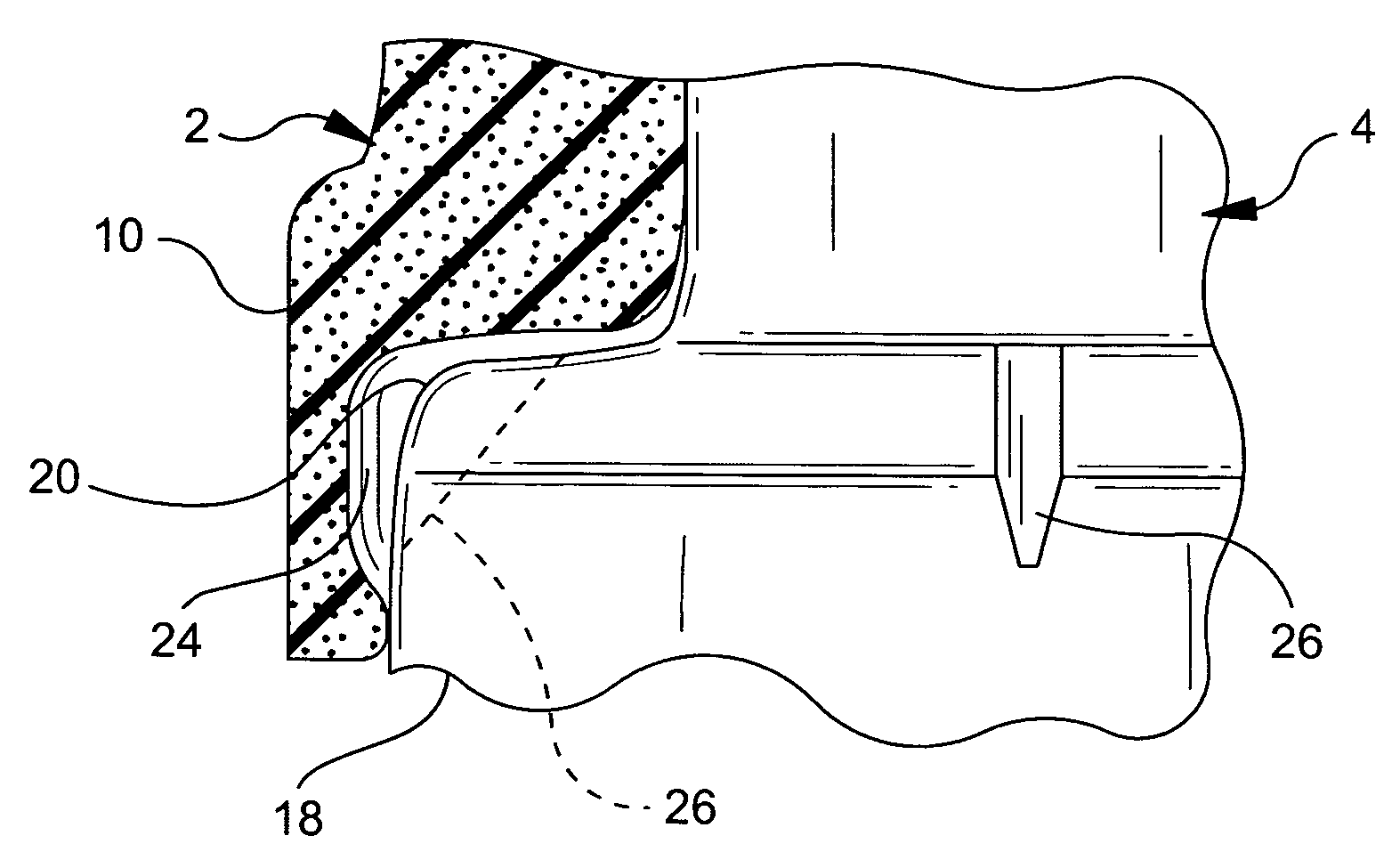
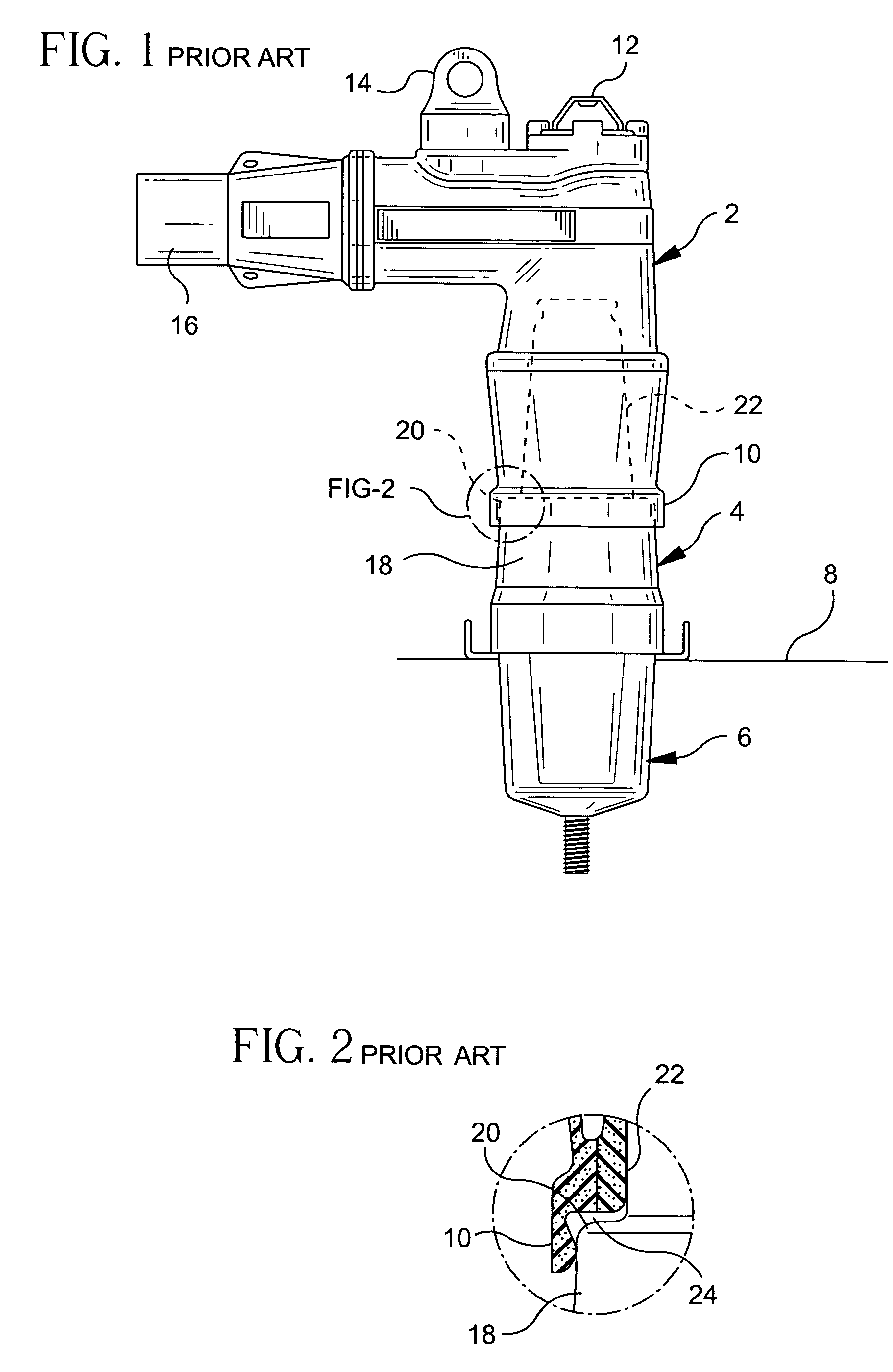
[0049]Referring to FIGS. 1 and 2, prior art loadbreak connectors are illustrated. In FIG. 1, a power cable elbow connector 2 is illustrated coupled to a loadbreak bushing insert 4 which is seated in a universal bushing well 6. The bushing well 6 is seated on an apparatus face plate 8. The power cable elbow connector 2 includes a first end adapted for receiving a loadbreak bushing insert 4 and having a flange or elbow cuff 10 surrounding the open receiving end thereof. The power cable elbow connector also includes an opening eye 12 for providing hot-stick operation and a test point 14 which is a capacitively coupled terminal used with appropriate voltage sensing devices. A power cable receiving end 16 is provided at the opposite end of the power cable elbow connector and a conductive member extends from the receiving end to the bushing insert receiving end for connection to a probe insertion end of the bushing insert.
[0050]Referring still to FIGS. 1 and 2, the loadbreak bushing inser...
PUM
Property
Measurement
Unit
operating voltage
aaaaa
aaaaa
operating voltage
aaaaa
aaaaa
operating voltage
aaaaa
aaaaa
Abstract
A method for forming a separable electrical connector having an electrical interface surface includes the steps of molding an interface shell from a thermoplastic, placing the interface shell against an electrical interface portion of a mold cavity and molding a housing within the mold cavity. When placed in the mold cavity, the interface shell provides a barrier to the mold cavity interface portion, wherein the housing is isolated from the electrical interface potion of the mold cavity by the interface shell. The shell has an inner surface and an outer surface and the housing is bonded to one of the inner and outer surfaces, wherein the other of the inner and outer surfaces of the shell defines the electrical interface surface of the electrical connector.
Description
CROSS-REFERENCE TO RELATED U.S. APPLICATIONS[0001]This application is a continuation-in-part of U.S. application Ser. No. 10 / 186,843, filed on Jul. 1, 2002, which is a continuation-in-part of U.S. application Ser. No. 09 / 715,571, filed on Nov. 17, 2000, now U.S. Pat. No. 6,585,531, which is a continuation of U.S. application Ser. No. 09 / 287,915, filed on Apr. 7, 1999, now U.S. Pat. No. 6,168,447, which is a continuation-in-part of Ser. No. 08 / 902,749, filed on Jul. 30, 1997, now U.S. Pat. No. 5,957,712.BACKGROUND OF THE INVENTION[0002]1. Field of the Invention[0003]The present invention relates to separable electrical connectors and more particularly to improvements in manufacturing separable electrical connectors, such as loadbreak connectors and deadbreak connectors, wherein a sleeve of low coefficient of friction material is provided during a molding process to protect the critical electrical interfaces of the connector from contamination. The sleeve further provides for ease of ...
Claims
Application Information
Patent Timeline
Application Date:The date an application was filed.
Publication Date:The date a patent or application was officially published.
First Publication Date:The earliest publication date of a patent with the same application number.
Issue Date:Publication date of the patent grant document.
PCT Entry Date:The Entry date of PCT National Phase.
Estimated Expiry Date:The statutory expiry date of a patent right according to the Patent Law, and it is the longest term of protection that the patent right can achieve without the termination of the patent right due to other reasons(Term extension factor has been taken into account ).
Invalid Date:Actual expiry date is based on effective date or publication date of legal transaction data of invalid patent.