
Optimization of ablation correction of an optical system and associated methods

a technology of optical system and ablation correction, which is applied in the field of optical aberration measurement and correction, can solve the problems of affecting system performance, deformation or distortion of reflected light waves exiting the eye, and affecting the performance of the system

Inactive Publication Date: 2006-05-16
ALCON INC
View PDF28 Cites 31 Cited by
  • Summary
  • Abstract
  • Description
  • Claims
  • Application Information

AI Technical Summary

Benefits of technology

[0012]The features that characterize the invention, both as to organization and method of operation, together with further objects and advantages thereof, will be better understood from the following description used in conjunction with the accompanying drawing. It is to be expressly understood that the drawing is fo

Problems solved by technology

In either case, aberrations in the optical system can affect the system's performance.
However, a real eye typically has aberrations that cause deformation or distortion of reflected light waves exiting the eye.

Method used


Image

  • Optimization of ablation correction of an optical system and associated methods
  • Optimization of ablation correction of an optical system and associated methods
  • Optimization of ablation correction of an optical system and associated methods

Examples


Embodiment Construction

[0029]A description of the preferred embodiments of the present invention will now be presented with reference to FIGS. 1–15.

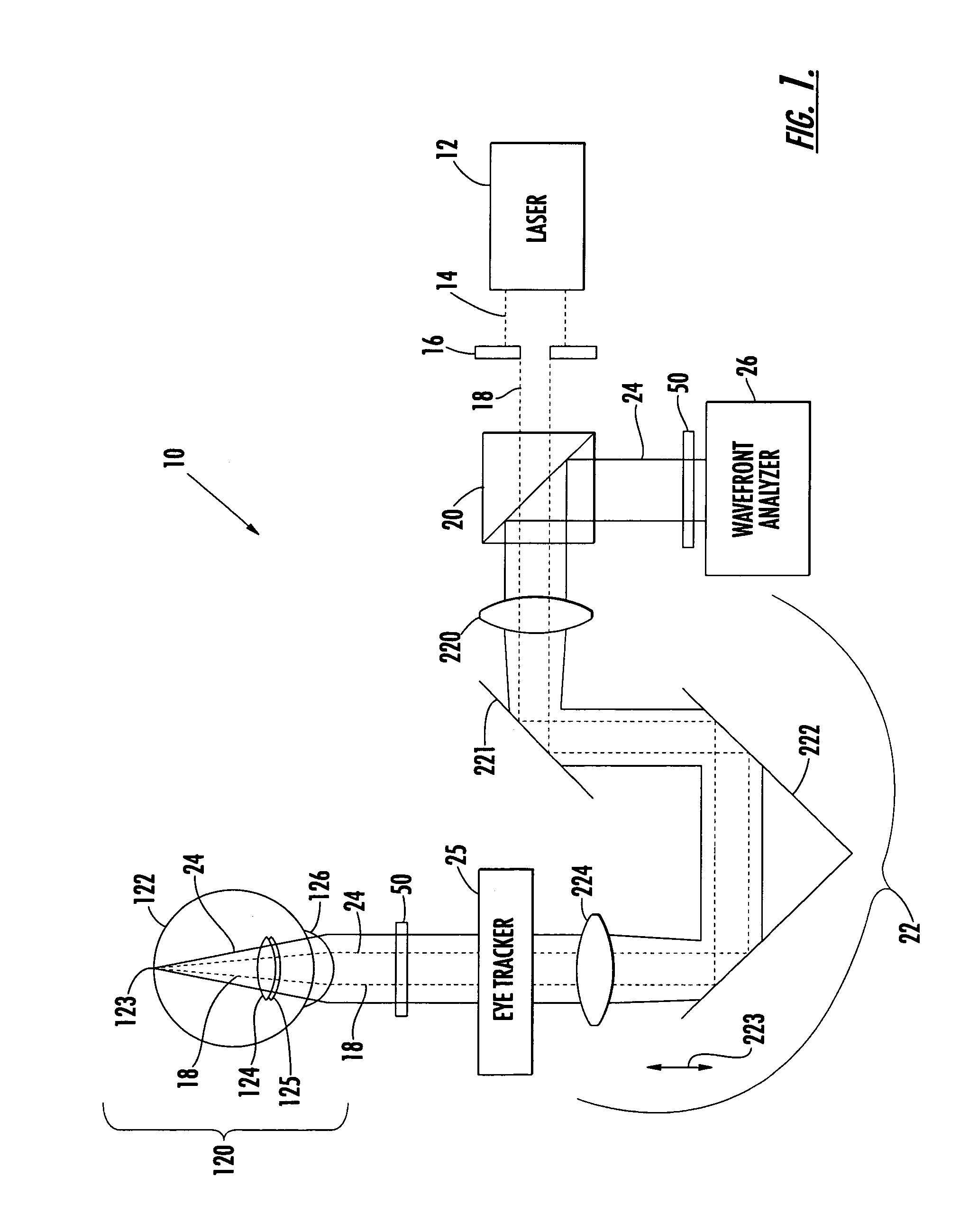
[0030]The system and method for correcting visual defects of an eye includes a wavefront analyzer, in a preferred embodiment a system 10 (FIG. 1) similar to that described in copending and co-owned application Ser. No. 09 / 664,128, the contents of which are incorporated herein by reference. The apparatus 10 includes a laser 12 for generating optical radiation used to produce a small-diameter laser beam 14. The laser 12 generates a collimated laser light beam (represented by dashed lines for the beam 14) of a wavelength and power that is eye-safe. For ophthalmic applications, appropriate wavelengths would include the entire visible spectrum and the near-infrared spectrum. By way of example, appropriate wavelengths may be in a range of from approximately 400–1000 nms, including 550-, 650-, and 850-nm useful wavelengths. While operation in the visible spectrum is ...


PUM


Abstract

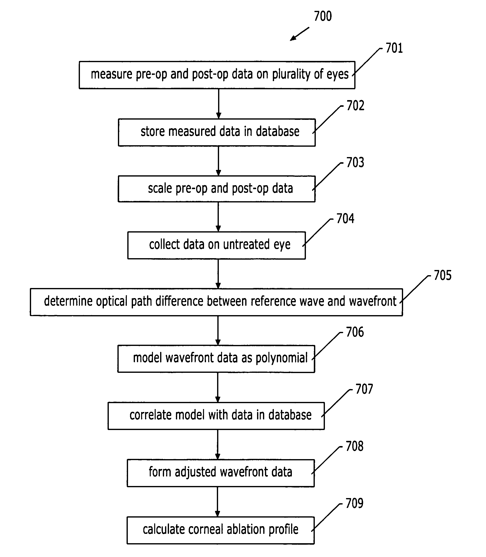
A system and method for converting measured wavefront data into an ablation profile for correcting visual defects includes providing measured wavefront data on an aberrated eye by a method such as known in the art. The measured wavefront data are correlated with accumulated data on previously treated eyes. Next an adjustment is applied to the measured wavefront data based upon the correlating step. This adjustment is used to form adjusted wavefront data for input to a wavefront data correction algorithm to calculate an ablation profile therefrom. The wavefront data correction algorithm may be modeled as, for example, Zernike polynomials with adjusted coefficients.

Description

CROSS-REFERENCE TO RELATED APPLICATION[0001]This application claims priority to provisional application Ser. No. 60 / 348,586, filed Jan. 14, 2002, for “Myopic Wavefront Treatment Optimization,” and also continuation-in-part to application Ser. No. 09 / 814,398, filed Mar. 22, 2001, now U.S. Pat. No. 6,569,154, for “Optimization of Ablation Correction of an Optical System and Associated Methods,” which itself claims priority to provisional application Ser. No. 60 / 191,187, filed Mar. 22, 2000, for “Optimizing Refractive Surgery Ablation Profiles by Compensating for Ablation Effectiveness Function,” all of which are commonly owned with the present invention and which are incorporated herein by reference.BACKGROUND OF THE INVENTION[0002]1. Field of the Invention[0003]The present invention relates to optical aberration measurement and correction, and, more particularly, to a system and method for achieving an empirical, global optimization of an objective measurement and correction of an op...

Claims


Application Information

Patent Timeline
IPC IPC(8): A61B18/18A61B18/00A61B3/103A61F9/007A61B5/103A61F9/01
CPCA61B3/1015A61F9/00806A61B5/103A61F2009/0088A61F2009/00857A61F2009/00872A61F2009/00846
Inventor CAMPIN, JOHN ALFREDPETTIT, GEORGE H.
Owner ALCON INC
Learn More