Oil separator for a welder

a technology of oil separator and welder, which is applied in the field of combined welder and compressor unit, and achieves the effect of efficient carrying

Inactive Publication Date: 2006-05-16
ILLINOIS TOOL WORKS INC
View PDF11 Cites 32 Cited by
  • Summary
  • Abstract
  • Description
  • Claims
  • Application Information

AI Technical Summary

Benefits of technology

[0008]Thus, with the present invention, an oil separator is provided that is relatively compact and yet efficiently carries out the function of separating oil from the stream of air containing that oil that is received from an air compressor. In the present invention, the oil separator has a arcuate housing, preferable cylindrical, and has a closed cover enclosing the upper portion of the housing and a bottom enclosing a lower portion. An inlet is located in the upper portion of the housing and through which the stream of fluid containing a quantity of entrained oil passes into the interior of the housing. A baffle or deflector directs that path of the flow of the oil laden stream to create an oil flow generally around the circular inner surface of that housing such that the oil tracks in a circular or spirally downwardly path aided by the force of gravity to eventually travel to the bottom of the housing. At the same time, the compressed air is caused to separate out and is allowed to flow upwardly through an outlet in the upper portion of the housing, preferably in the closed cover of that housing.

Problems solved by technology

That stream, however, may contain a large quantity of oil and which is not desirable for most end uses and, additionally, it is important to recover that oil to reuse the oil in order to efficiently operate the welder and compressor unit.

Method used


Image

  • Oil separator for a welder
  • Oil separator for a welder
  • Oil separator for a welder

Examples


Embodiment Construction

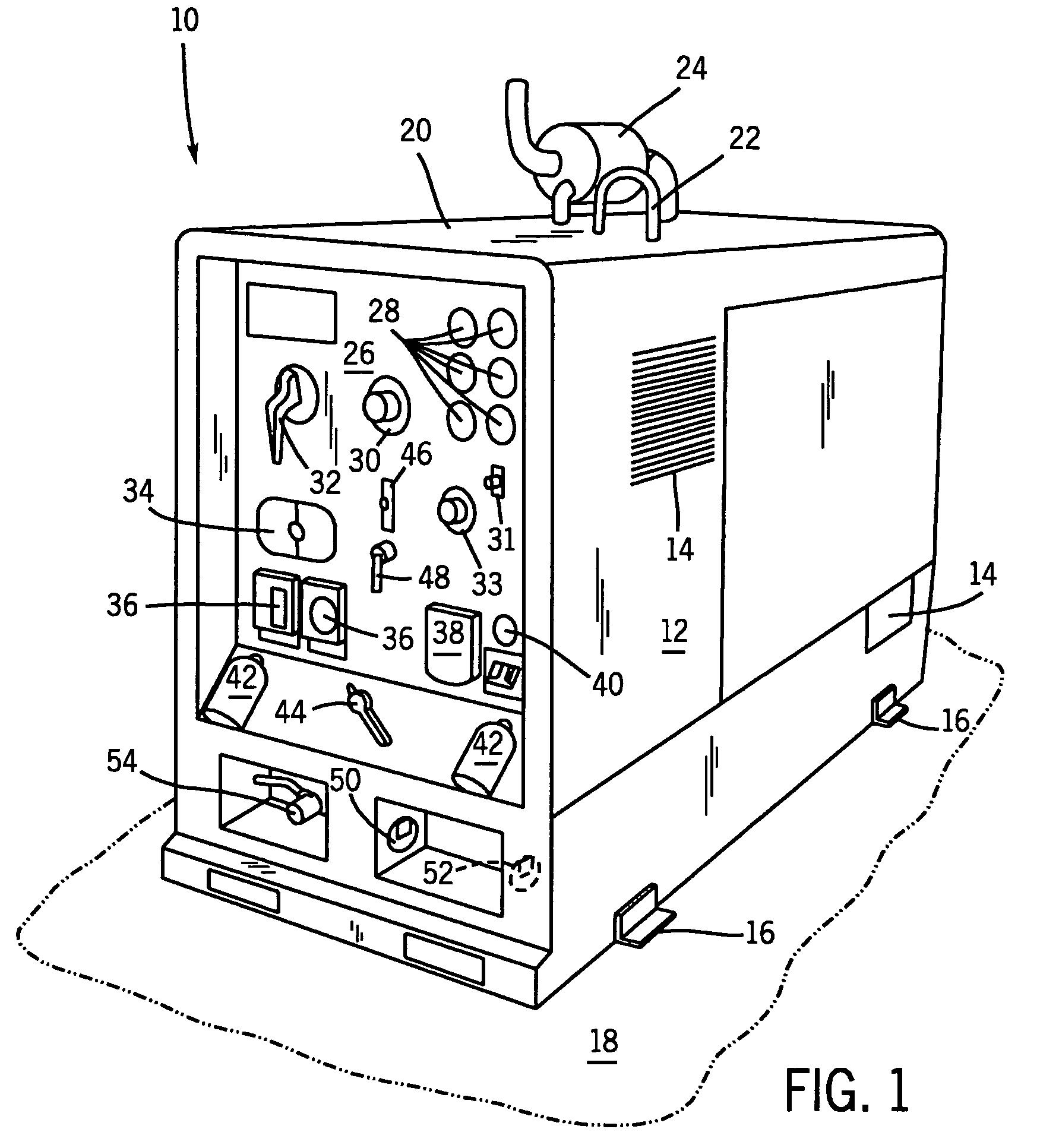
[0024]Referring now to FIG. 1, a portable engine-driven welder and compressor combination or system 10 is provided. The welder combination 10 has an outer housing 12 that has one or more air vents 14 for cooling internal components of the welder combination 10. The housing 12 can be easily removed to permit access to the internal components for maintenance and service. A plurality of support members 16 provide stabilization for the welder combination 10 when placed on a generally level surface, such as surface 18. An upper surface 20 of the welder combination 10 includes a lifting hook 22 extending therethrough for lifting and transporting of the welder combination 10. Also attached to the upper surface 20 is an exhaust system 24 that lowers noise and removes exhaust gas from the welder combination 10.

[0025]The welder combination 10 includes a control panel 26 that has various control elements and gauges for operating the welder combination 10. A plurality of gauges 28 measure vario...


PUM

PropertyMeasurementUnit
diameteraaaaaaaaaa
perimeteraaaaaaaaaa
elevationaaaaaaaaaa

Abstract

An oil separator usable with a welder and air compressor combination unit. The oil separator includes a cylindrical housing having an inlet that receives the stream of compressed air containing oil from the air compressor. Within the oil separator, there is a deflector baffle that redirects the flow of the oil to a swirling, downwardly directed path along the inner surface of the cylindrical housing where the air is separated out therefrom and passes upwardly to exit through a fluid outlet formed in the cover of the separator. The swirling oil flows downwardly through an annular slot formed between a circular plate and the inner surface of the cylindrical housing into a lower chamber where the oil is channeled by radially directed baffles into radial channels to redirect that oil toward an oil outlet at the center of the circular bottom where that oil exits to be re-circulated in the combination unit or for disposal.

Description

CROSS-REFERENCE TO RELATED APPLICATION[0001]This application is a divisional of, and claims priority to, allowed U.S. Ser. No. 10 / 191,335, filed Jul. 8, 2002 now U.S. Pat. No. 6,753,503.BACKGROUND OF THE INVENTION[0002]The present invention relates generally to combined welder and compressor units, and more particularly to a unit of this type having an oil separator for separating oil from a pressurized fluid containing oil.[0003]Portable welding and compressor units transportable to a work site are known. Typical known units include a lightweight frame consisting of metal tubing on which is mounted an internal combustion engine that is directly connected to a generator which generates an amperage to operate the unit or welder. The generator further provides auxiliary alternating current for operating auxiliary equipment, such as an air compressor. The air compressor provides compressed air for pneumatic equipment as well as certain welding applications, such as operating a plasma c...

Claims


Application Information

Patent Timeline
Patent Type & Authority Patents(United States)
IPC IPC(8): B01D45/12B23K7/10B23K9/32
CPCB23K7/10B23K9/32Y10T29/49229
Inventor BANKSTAHL, HERBERT A.GITTER, JOSEPH
Owner ILLINOIS TOOL WORKS INC
Why Eureka
Try Eureka