

Cell plate structure for fuel cell, manufacturing method thereof and solid electrolyte type fuel cell
a cell plate and fuel cell technology, applied in the direction of cell components, final product manufacturing, sustainable manufacturing/processing, etc., can solve the problems of difficult control of manufacturing conditions, poor porosity rate of electrode plates, and inability to achieve comparable improvement in production yield, etc., to achieve suitable porosity rate, reduce porosity rate, and adequate strength
- Summary
- Abstract
- Description
- Claims
- Application Information
AI Technical Summary
Benefits of technology
Problems solved by technology
Method used
Image

Examples
example 1
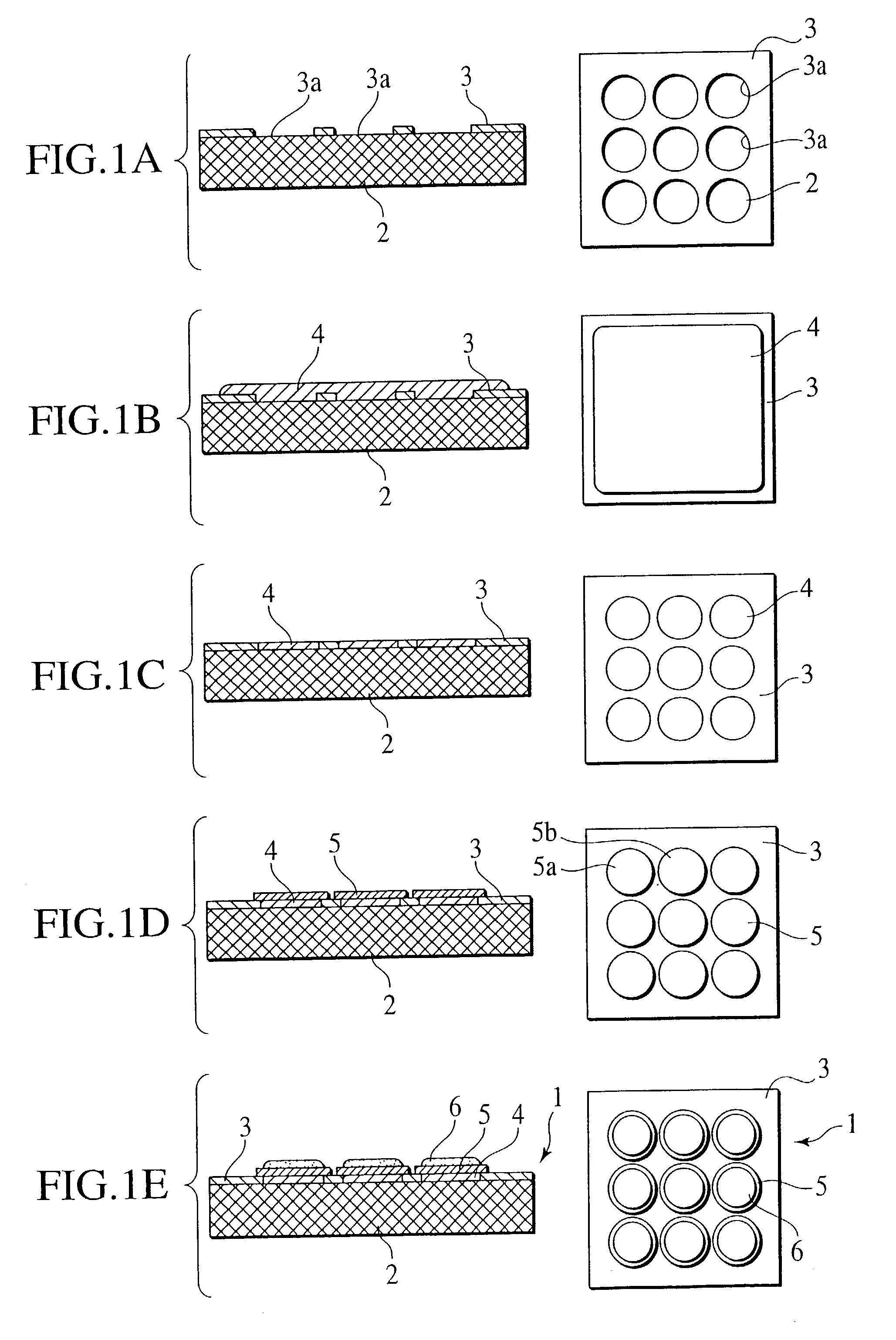
[0059]FIGS. 1A to 1E are cross sectional views and related plan views for sequentially illustrating manufacturing steps for the cell plate structure 1 for the fuel cell of the first example (EXAMPLE 1) of the preferred embodiment according to the present invention, with the cross sectional views bearing at the left sides of these drawings while the plan views are illustrated at the right sides of these drawings, respectively.
[0060]In the cell plate structure 1 for the fuel cell of the preferred embodiment, initially as shown in FIG. 1A, a Ni foil of a thickness of 10 μm was brazed as a gas impermeable layer 3 onto a porous metallic substrate 2 made of SUS material (stainless steel) with a thickness of 2 mm, a porosity rate of 70% and an average pore diameter of 5 μm using Ni-base alloy brazing paste. Also, the Ni foil 3 was preliminarily formed with a plurality of bores 3a with a diameter of 4 mm.
[0061]Subsequently, as shown in FIG. 1B, a Ni layer serving as the lower electrode laye...
example 2
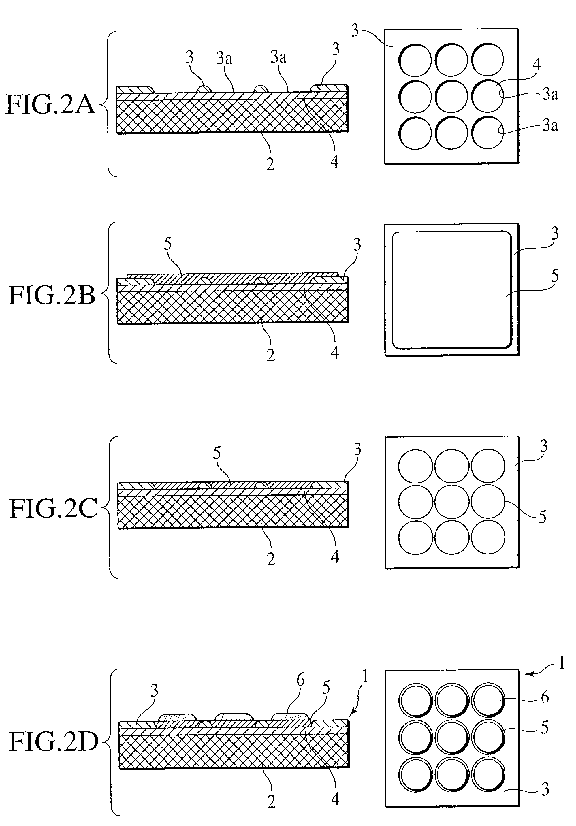
[0067]FIGS. 2A to 2D are cross sectional views and related plan views for sequentially illustrating manufacturing steps for the cell plate structure 1 for the fuel cell of the second example (EXAMPLE 2) of the preferred embodiment according to the present invention, with the cross sectional views bearing at a left side of the drawings while the plan views are illustrated in right side.
[0068]In the cell plate structure 1 for the fuel cell of this EXAMPLE, initially as shown in FIG. 2A, a film of LSM having a thickness of 30 μm and serving as a lower electrode layer 4 was formed over an entire surface of a porous substrate 2 made of zirconia with a thickness of 2 mm, the pore rate of 40% and an average pore diameter of 2 μm by plasma spraying method. And, a Ni foil was brazed onto the lower electrode layer 4 as a gas impermeable layer 3 using Ni-base alloy brazing paste added with Ti. Also, the Ni foil 3 was preliminarily conditioned to have a pattern including a plurality of bores 3a...
example 3
[0073]FIG. 3 is a cross sectional view and a related plan view for illustrating a cell plate structure 1 for the fuel cell of the third example (EXAMPLE 3) of the preferred embodiment according to the present invention, with the cross sectional views bearing at the left side of this drawing while the plan view is illustrated at the right side of this drawing.
[0074]The cell plate structure 1 of this EXAMPLE was similar to the cell plate structure 1 for the fuel cell produced in EXAMPLE 2 in that a lower electrode layer 4 was formed on an entire surface of a porous substrate 2 and a gas impermeable layer 3 was formed on the lower electrode layer 4, but was different from EXAMPLE 2 in that the gas impermeable layer was designed to have a profile with sharp edges in cross section. That is, the presence of the gas impermeable layer 3 formed with the sharp cross sectional shape appearing in EXAMPLE 3 caused cracks to be created into divided pieces at desired areas in a given pattern in th...
PUM
| Property | Measurement | Unit |
|---|---|---|
| Electrical conductivity | aaaaa | aaaaa |
| Porosity | aaaaa | aaaaa |
| aaaaa | aaaaa |
Abstract
Description
Claims
Application Information