Interconnection assembly for an electric motor and method of making the same

a technology of interconnection assembly and electric motor, which is applied in the direction of dynamo-electric components, windings, synchronous machines, etc., can solve the problems of increasing manufacturing costs, affecting the performance of insulation, and severely changing the carrying capacity of current, etc., and achieves the effect of suppressing strain

Inactive Publication Date: 2006-05-16
HITACHI CABLE +1
View PDF12 Cites 23 Cited by
  • Summary
  • Abstract
  • Description
  • Claims
  • Application Information

AI Technical Summary

Benefits of technology

[0011]It is an object of the invention to provide an interconnection assembly that can suppress strain caused by a difference in thermal expansion between lead frame and molded resin.
[0012]It is another object of the invention to provide an interconnection assembly that waste part in manufacturing the lead frame can be reduced.

Problems solved by technology

In motors, especially then it starts and during the normal operation, the current-carrying capacity changes severely.
Thus, when the current-carrying capacity changes severely, there may occur a crack in the molded resin 27 that is mechanically weak and has a great expansion coefficient and, therefore, the insulation performance may be broken.
Thus, loss of material increases and lowering of yield causes an increase in manufacturing cost.

Method used


Image

  • Interconnection assembly for an electric motor and method of making the same
  • Interconnection assembly for an electric motor and method of making the same
  • Interconnection assembly for an electric motor and method of making the same

Examples


Embodiment Construction

[0034]FIG. 4A is a plain view showing an interconnection assembly parts in the preferred embodiment according to the invention

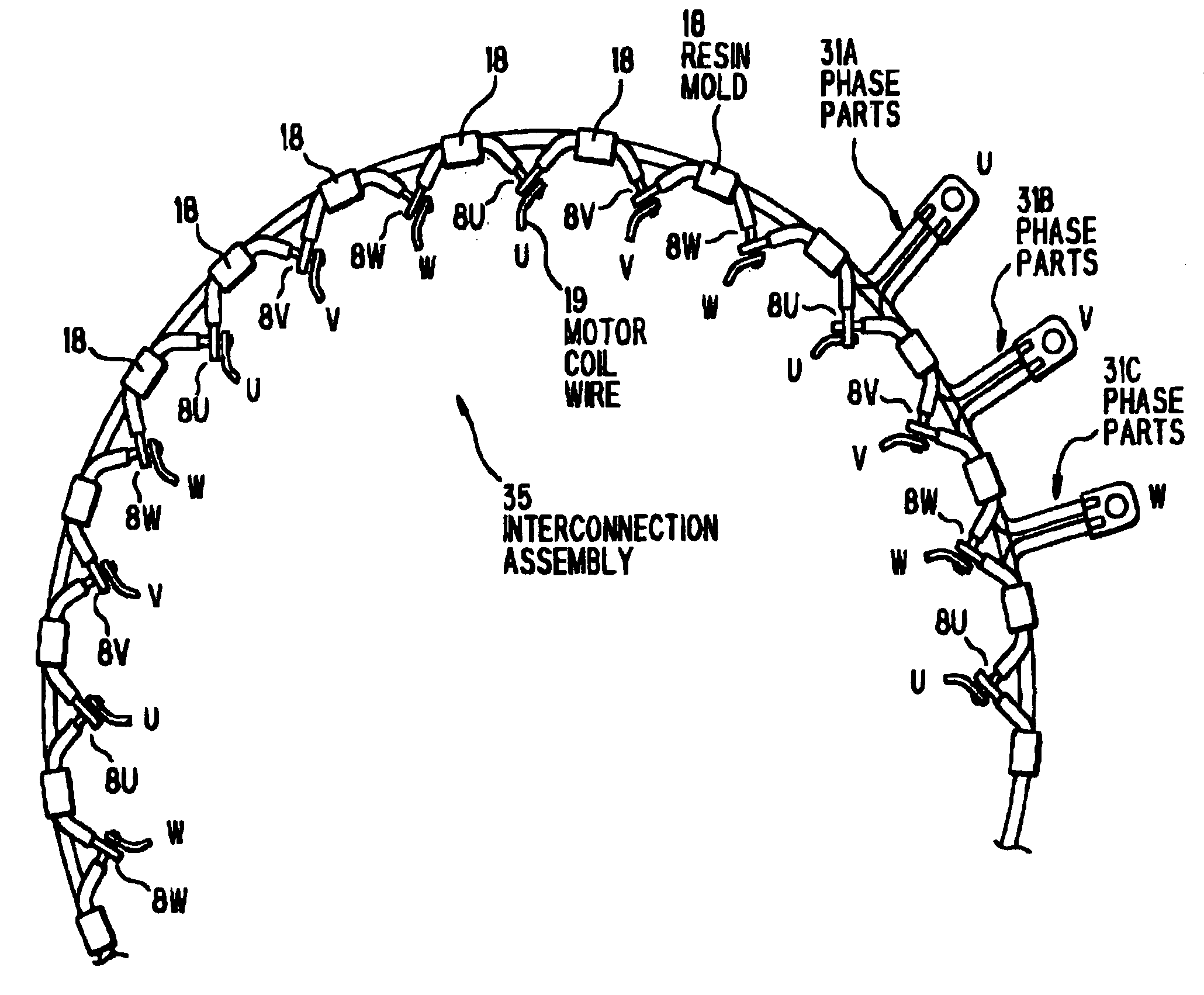
[0035]In FIG. 4A, 10 indicates an interconnection assembly parts. The interconnection assembly parts 10 is made by cutting a predetermined length of an insulated wire 9 that is of a single-wire conductor 8 covered with a fluororesin insulation 8A (e.g., PFA, PTFE, ETFE, PEP and PVTF), removing the fluororesin insulation 8A at both ends of the insulated wire 9 to expose the single-wire conductor 8, folding the exposed ends to have a predetermined angle θ.

[0036]The insulated wire 9 is desirably of the single-wire conductor 8 with a diameter of 1 to 5 mm with the fluororesin insulation 8A.

[0037]FIGS. 4B and 4C are side views showing end part of the interconnection assembly parts in FIG. 4A.

[0038]As shown in FIGS. 4A and 4B, the single-wire conductor 8 with the exposed ends is, for facilitating the welding on the subsequent stage, pressed to have the ends formed ...


PUM


Abstract

An interconnection assembly has phase parts for U phase, V phase and W phase. The phase parts each are of a plurality of interconnection assembly parts that are connected in the form of a ring and include a conductor section to which a motor coil wire is connected, the conductor section being formed by stripping fluororesin insulation at a predetermined position, and the phase parts are partially fixedly bundled.

Description

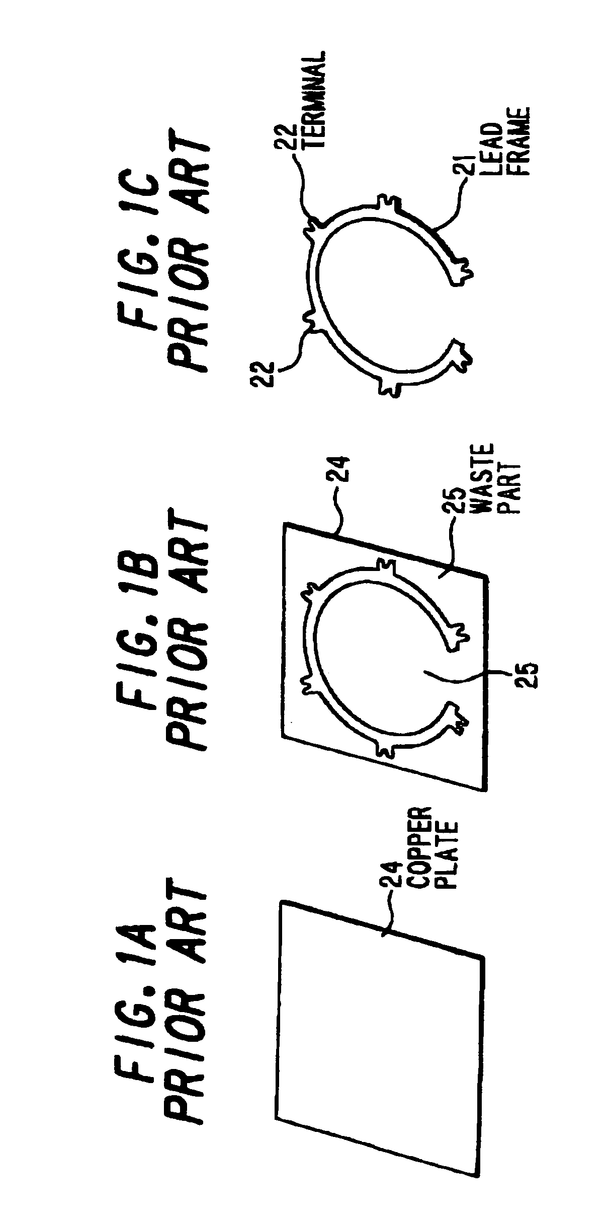
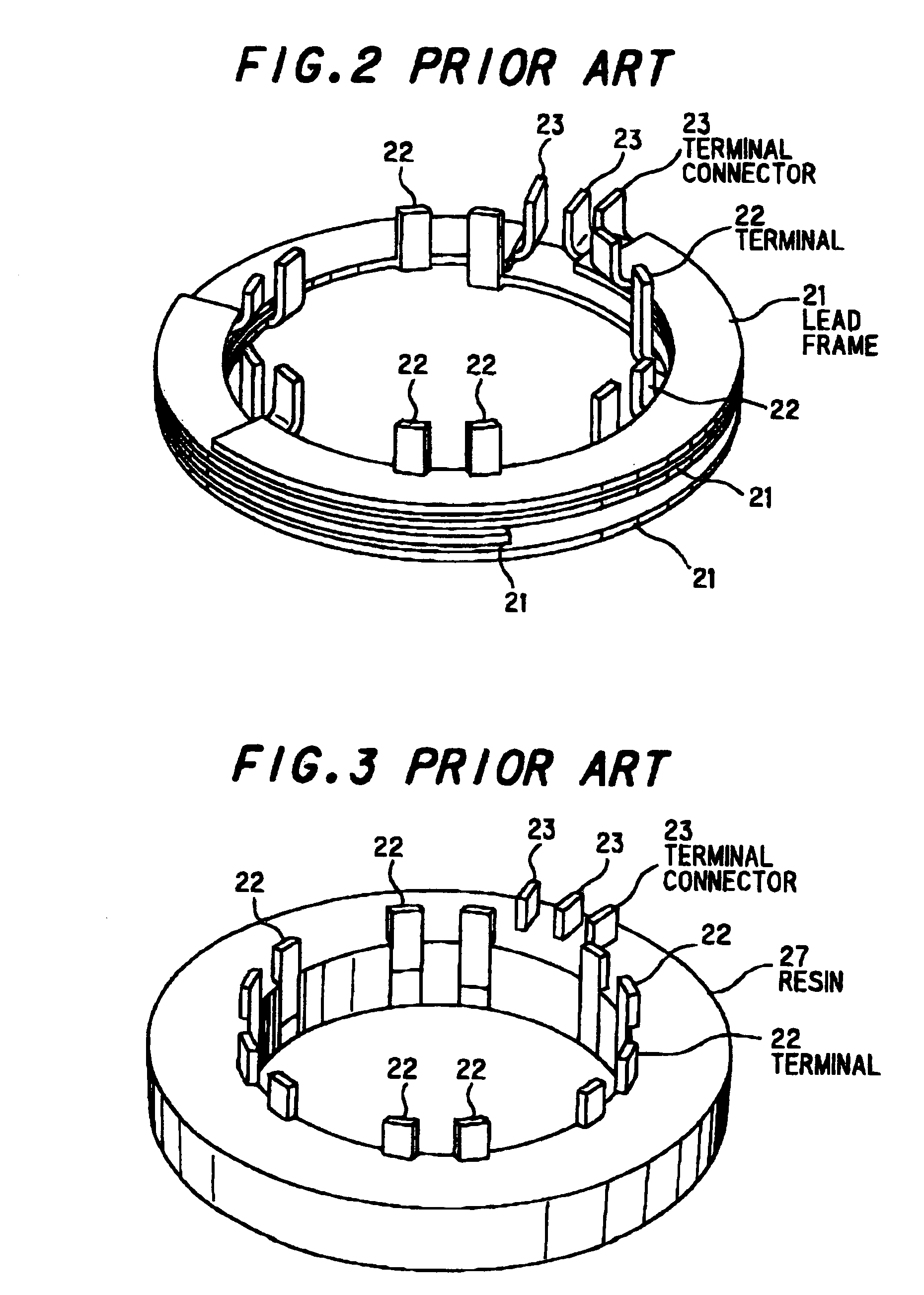
[0001]The present application is based on Japanese patent application No. 2002-240741, the entire contents of which are incorporated herein by reference.BACKGROUND OF THE INVENTION[0002]1. Field of the Invention[0003]This invention relates to an interconnection assembly used for a motor of, e.g., an electric car to connect with the motor coil wire, and relates to a method of making the same.[0004]2. Description of the Related Art[0005]Conventional interconnection assemblies used to connect with the motor coil wire are made as follows. At first, a square copper plate 24 as shown in FIG. 1A is punched by pressing as shown in FIG. 1B, thereby giving a lead frame as shown in FIG. 1C. Then, as shown in FIG. 2, four lead frames 21 for U phase, V phase, W phase and grounding are stacked with a gap of about 0.5 to 2 mm in the vertical direction Finally, as shown in FIG. 3, the lead frame 21 is placed in a molding die (not shown) and is then molded with super-engineering molding resin 27.[00...

Claims


Application Information

Patent Timeline
Patent Type & Authority Patents(United States)
IPC IPC(8): H02K3/04H02K15/04H02K3/50
CPCH02K3/50H02K2203/09
Inventor OHUCHI, KATSUAKIENDO, KATSUOMATSUO, HIDEOKABASAWA, AKIRAOKAMURA, AKIHIROTAKAHASHI, KAZUNARI
Owner HITACHI CABLE
Why Eureka
Try Eureka