Holder for cathode ray tube and fabrication method thereof

a technology fabrication method, which is applied in the direction of cathode ray tube/electron beam tube, coupling device connection, mechanical apparatus, etc., can solve the problems of limited resolution and image quality of visualized techniques, and achieve the effect of reducing material cost, reducing waste, and eliminating unnecessary scraps or waste materials

Inactive Publication Date: 2006-05-16
MERIDIAN SOLAR & DISPLAY
View PDF8 Cites 3 Cited by
  • Summary
  • Abstract
  • Description
  • Claims
  • Application Information

AI Technical Summary

Benefits of technology

[0015]Therefore, an object of the present invention is to provide a holder for a cathode ray tube, in which a pair of holders are integrally formed by an efficient punching and slitting process, e.g., that eliminates the unnecessary generation of scrap or waste material to reduce material cost
[0016]An additional object of the present invention is to strengthen an engaging force between the holder and a stud pin, and thus to improve noise generated by external vibration with the apparatus and fabrication method of the present invention.

Problems solved by technology

In the cathode ray tube of the background art, visualized techniques such as resolution and image quality are limited.

Method used


Image

  • Holder for cathode ray tube and fabrication method thereof
  • Holder for cathode ray tube and fabrication method thereof
  • Holder for cathode ray tube and fabrication method thereof

Examples


Embodiment Construction

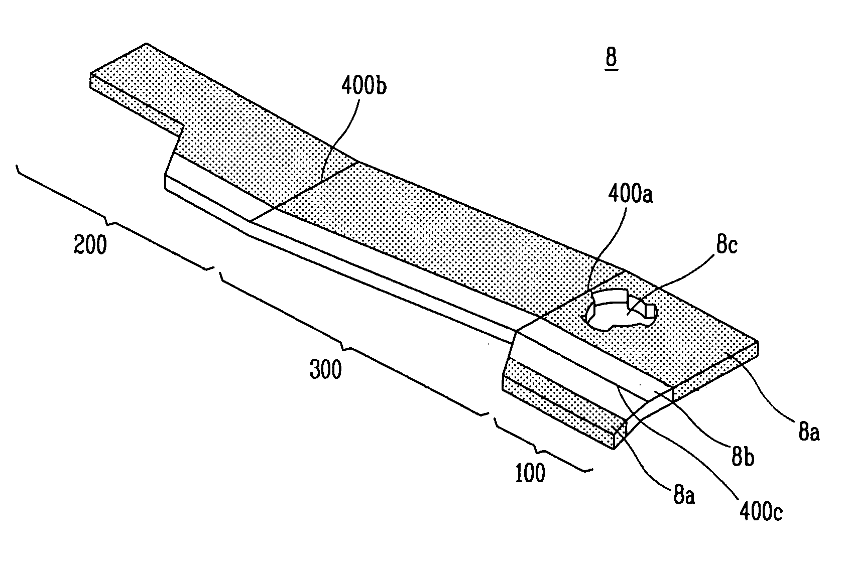
[0031]Reference will now be made in detail to the preferred embodiments of the present invention, examples of which are illustrated in the accompanying drawings. FIG. 4 is a view showing a shape of a holder for a cathode ray tube according to an embodiment of the present invention. FIG. 5 is a view showing each lower end surface of a respective holder for a cathode ray tube of the present invention arranged facing to each other. FIG. 6 is a view showing an individual holder for a cathode ray tube according to an embodiment of the present invention. FIGS. 7A, 7B, 7C, 7D, 7E, 7F, and 7G are views showing a fabrication process of the holder for a cathode ray tube according to an embodiment of the present invention. FIGS. 8A and 8B are views showing a holder for a cathode ray tube engaged with a shadow mask assembly according to an embodiment of the present invention.

[0032]As shown in FIG. 4, a holder 8 for a cathode ray tube includes a stud engaging portion 100 having an engaging hole ...


PUM


Abstract

A holder for a cathode ray tube includes a stud engaging portion having an engaging hole in order to be engaged to a stud pin mounted inside a panel, a frame engaging portion engaged to a mask frame which supports a shadow mask, and a connecting portion for connecting the stud engaging portion and the frame engaging portion. Lower end surfaces of a pair of holders are arranged facing toward each other so that the lower end surfaces of the connecting portion are in substantial contact with each other.

Description

[0001]This nonprovisional application claims priority under 35 U.S.C. §119(a) on Patent Application No(s). 29877 / 2003 filed in Korea on May 12, 2003, which is(are) herein incorporated by reference.BACKGROUND OF THE INVENTION[0002]1. Field of the Invention[0003]The present invention relates to a holder for a cathode ray tube and a fabrication method thereof, and more particularly, to a holder and a fabrication method thereof for a cathode ray tube which can reduce fabrication costs by integrally forming a pair of holders during a punching process for forming the holder. Accordingly, the generation of unwanted scrap is prevented during the fabrication of the holder.[0004]2. Description of the Background Art[0005]A cathode ray tube is a device for converting an electric signal into an electron beam and emitting the electron beam to a phosphor screen to realize an image. The cathode ray tube is widely used in the background art since excellent display quality is achieved at an affordabl...

Claims


Application Information

Patent Timeline
Patent Type & Authority Patents(United States)
IPC IPC(8): H01J29/80H01J29/02H01J29/07
CPCH01J29/073H01J29/02
Inventor KO, MIN-HEEKANG, SANG-HYUNG
Owner MERIDIAN SOLAR & DISPLAY
Why Eureka
Try Eureka